


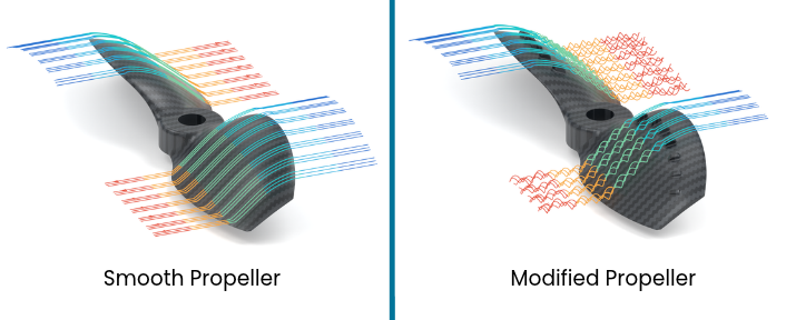
Surface modifications intended to improve airflow attachment do not necessarily increase propeller efficiency. In a series of comparative tests, Tyto Robotics examined how adding vortex generators to a small UAV propeller affected thrust, torque, and power efficiency under different airflow conditions. The results showed that the modified propeller generally produced less thrust and required more torque than an equivalent smooth propeller, highlighting the challenges of applying boundary layer control techniques to rotating blades.
The experiment investigated whether small raised features on the blade surface could delay airflow separation and improve aerodynamic performance. Although similar approaches have shown benefits on stationary airfoils, the tests demonstrated that their effectiveness cannot be assumed when applied to propellers.
Understanding Boundary Layer Behavior on Propeller Blades
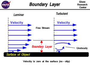
Boundary layer formation with laminar and turbulent flows
The boundary layer is a thin region of air immediately adjacent to an aerodynamic surface, where airflow velocity changes from zero relative to the surface to the velocity of the surrounding airflow.
On a propeller blade, air molecules in direct contact with the surface have zero relative velocity because of the no-slip condition. Moving outward from the blade, airflow velocity progressively increases until it approaches the free-stream velocity.
Despite its small thickness, the boundary layer influences skin-friction drag, airflow separation, lift generation, thrust, and power consumption.
One factor governing boundary layer behavior is the Reynolds number, a dimensionless quantity that describes the relationship between inertial and viscous forces in a fluid.
Lower Reynolds numbers generally favor laminar flow, characterized by comparatively orderly movement of air. Higher Reynolds numbers make the transition to turbulent flow more likely, although surface roughness, geometry, and disturbances in the incoming airflow also influence this transition.
These characteristics are particularly important when considering how changes to a blade surface might affect aerodynamic performance.
How Boundary Layer Separation Affects Lift
Airfoils generate lift through a combination of pressure differences around their surfaces and the deflection of airflow.
The boundary layer contributes to this process by influencing how closely the airflow follows the airfoil’s shape. When the flow remains attached, it supports the pressure distribution responsible for lift generation.
Separation occurs when the boundary layer can no longer remain attached to the surface. The resulting change in pressure distribution can reduce lift and, if separation becomes sufficiently extensive, lead to stall.
Several factors influence the location and onset of separation, including airfoil geometry, Reynolds number, surface roughness, and angle of attack.
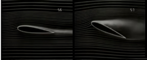
The airfoil on the left has a low angle of attack, allowing the airflow to remain attached to the surface for longer. The airfoil on the right has a higher angle of attack, which causes the airflow to separate and the airfoil to stall
The angle of attack is the angle between an airfoil’s chord line and the direction of the incoming airflow. Increasing this angle can produce a stronger adverse pressure gradient, making it more difficult for the boundary layer to remain attached.
As separation develops, the airfoil may experience reduced aerodynamic performance and eventually stall.
Delaying separation can therefore be beneficial in operating conditions where airflow attachment becomes difficult to maintain.
Using Surface Features to Delay Flow Separation
One established example of boundary layer modification is the dimpled surface of a golf ball.
Although laminar flow generally produces less skin-friction drag than turbulent flow, a laminar boundary layer has less momentum near the surface and can separate relatively early from a curved object.
On a smooth golf ball, early separation produces a large low-pressure wake behind the ball, increasing pressure drag.
Dimples introduce small disturbances that encourage the boundary layer to transition to turbulent flow. Turbulent mixing brings higher-momentum air closer to the surface, allowing the flow to remain attached farther around the ball.
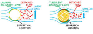
Aerodynamics of a golf ball with and without dimples
This reduces the size of the wake and the associated pressure drag.
The tradeoff is increased skin-friction drag within the turbulent boundary layer. However, the reduction in pressure drag can outweigh this increase, producing a net reduction in aerodynamic drag.
The same principle does not automatically apply to aircraft wings.
Unlike golf balls, aircraft wings have streamlined profiles intended to generate lift while maintaining attached airflow across much of their operating range. Introducing additional surface disturbances can therefore increase drag without providing sufficient aerodynamic benefit.
Nevertheless, carefully positioned surface features can improve performance under certain conditions.
Vortex Generators on Aircraft Wings
Vortex generators are small vanes mounted on aerodynamic surfaces to deliberately introduce vortices into the boundary layer.
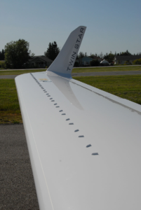
Micro vortex generators on a small airplane wing
These vortices promote mixing between higher-momentum airflow away from the surface and slower-moving air near the surface. This can help the boundary layer resist separation when operating under challenging aerodynamic conditions.
Vortex generators also introduce additional drag. Their usefulness therefore depends on whether improvements in lift, stall characteristics, or control effectiveness outweigh the resulting drag penalty.
Conditions in which vortex generators may provide benefits include:
- Low-speed flight
- High angles of attack
- Takeoff
- Approach
- High-speed maneuvering
Their effectiveness depends on factors such as geometry, dimensions, position, and the local aerodynamic conditions.
Applying Boundary Layer Control to Propellers
Research conducted at Khulna University of Engineering & Technology provided the basis for the propeller experiment.
The researchers examined the effect of adding hexagonal dimples to a NACA-4415 airfoil, investigating whether the modified surface could delay flow separation at higher angles of attack.
According to the published research, flow separation occurred at an angle of attack of 12 degrees on the unmodified airfoil, compared with 16 degrees on the dimpled configuration.
The surface pressure distributions also differed. At a corresponding location on the airfoils, the modified configuration exhibited a more negative pressure coefficient on the suction side than the regular airfoil.
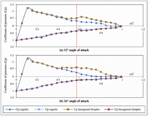
Surface pressure distribution of regular airfoil vs hexagonal dimpled airfoil at 12 and 16 degrees angle of attack
These findings suggested that deliberate boundary layer disturbances could improve aerodynamic performance under certain operating conditions.
Tyto Robotics investigated whether a related approach could produce measurable benefits on a rotating propeller.
Two 3D-printed, 4-inch propellers were manufactured with identical base blade geometry. One retained a smooth surface, while the other incorporated small raised vortex generators along the leading edge on the suction, or upper, side of each blade.
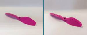
Tyto Robotics’ 3D-printed propellers with a smooth surface and with vortex generators
Both propellers used a relatively high blade pitch to investigate operating conditions in which airflow separation might occur.
The underlying hypothesis was that the raised features could increase momentum within the boundary layer, delay separation, and improve overall propeller efficiency.
The comparison was intended to determine whether the aerodynamic benefits observed on modified stationary airfoils could also be achieved on small propeller blades.
Experimental Setup and Performance Measurements
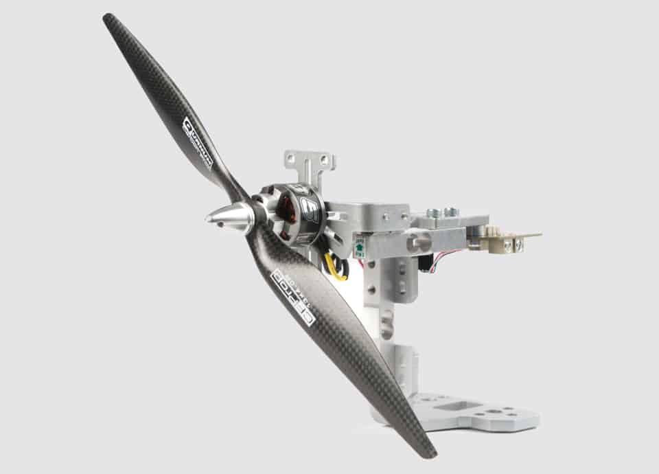
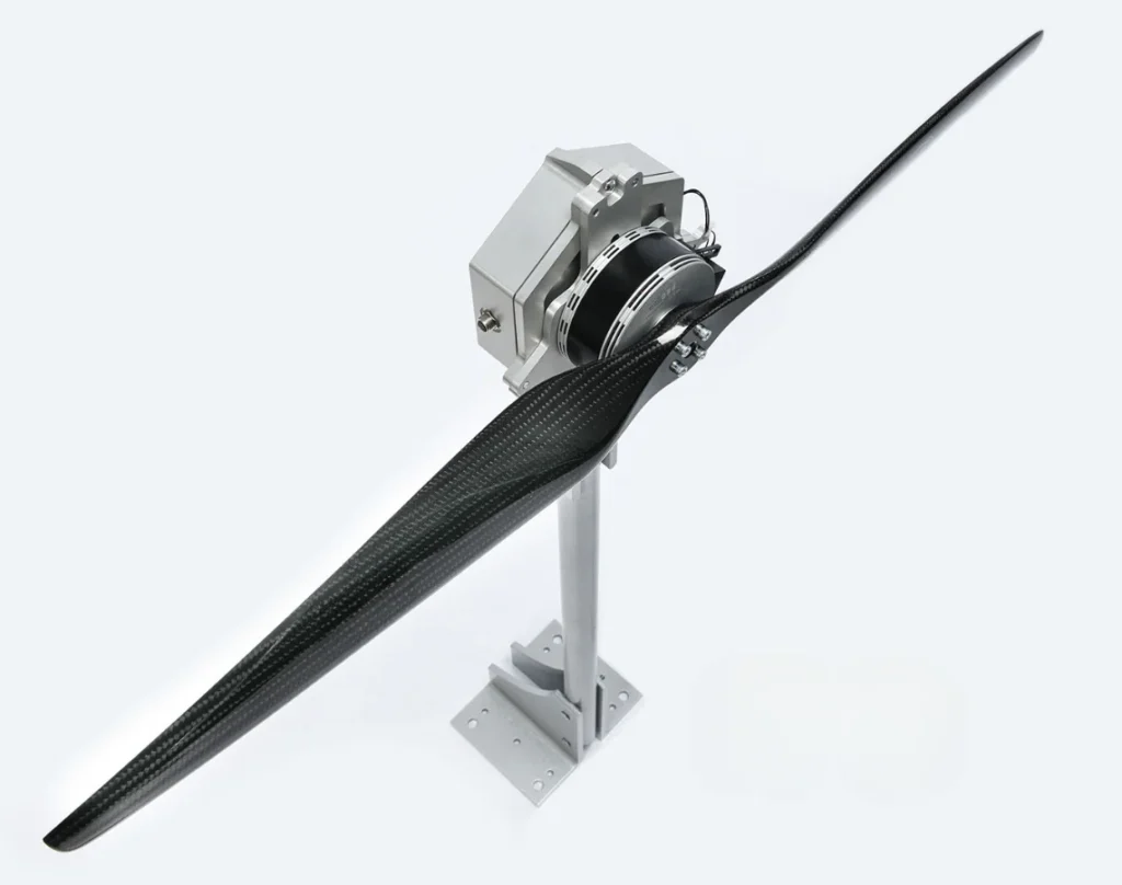
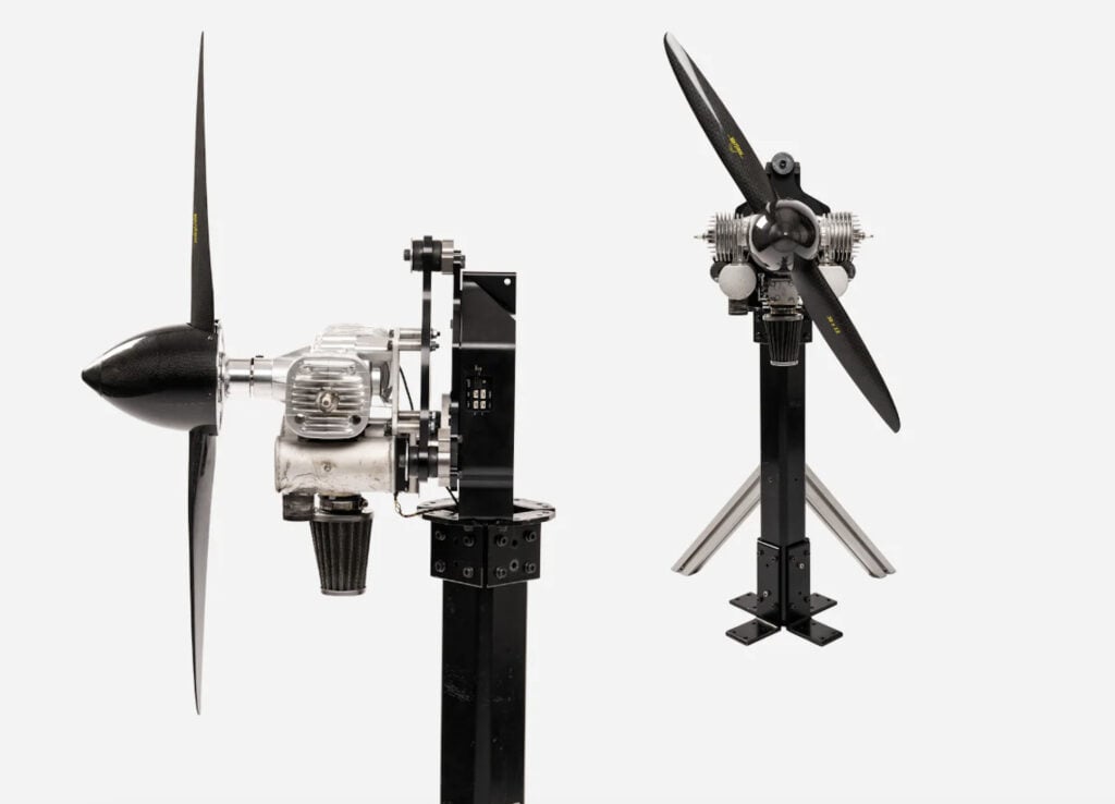
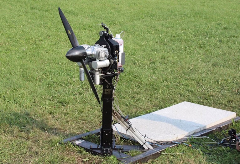
The two propellers were tested using a Series 1585 thrust stand, positioned in front of a 2×2 WindShaper.
Three airflow conditions were investigated:
1. No wind
2. Laminar flow
3. Turbulent flow
The WindShaper was maintained at a constant setting during the airflow tests, with an average wind speed of 8 m/s (28.8 km/h) for both laminar and turbulent conditions.
Data collection and test control were performed using Flight Stand Software.
The software’s automatic control function was used to perform a seven-step throttle test, progressing from 1,000 μs to 1,750 μs. The highest throttle setting corresponded to a maximum rotational speed of approximately 12,000 RPM, providing a practical operating range for the 4-inch propellers.
Four performance parameters were recorded:
- Thrust
- Torque
- Rotational speed
- Overall thrust efficiency
The efficiency metric was expressed as grams-force of thrust produced per watt of power supplied to the system. Recorded data was exported in .CSV format for subsequent analysis.
Importantly, the experiment did not directly measure boundary layer transition or separation. Consequently, possible explanations relating to the aerodynamic mechanisms behind the measured differences remain hypotheses rather than experimentally confirmed findings.
Thrust Performance Across Different Airflow Conditions
The smooth propeller generally produced more thrust than the modified propeller across the tested rotational speed range.
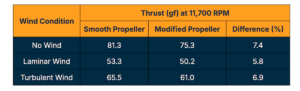
At approximately 11,700 RPM, the modified propeller generated between 5.8% and 7.4% less thrust than the smooth configuration, depending on the airflow condition.
Under no-wind conditions, both propellers generated similar thrust at lower rotational speeds. However, the difference increased with RPM, with the smooth propeller producing more thrust at higher speeds.
A comparable trend appeared under laminar flow, although the overall difference between the two configurations remained smaller.
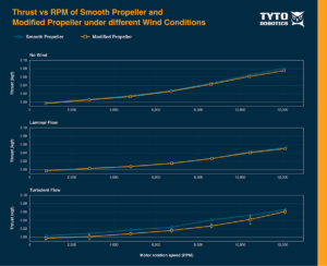
The clearest distinction was observed under turbulent flow. In this condition, the smooth propeller consistently produced more thrust across most of the tested RPM range.
The similarities between the no-wind and laminar-flow results may be associated with the relatively steady aerodynamic loading experienced by the blades.
Turbulent incoming airflow introduces variations in airspeed and direction, potentially changing the local operating conditions experienced by the rotating propeller.
Torque Requirements of the Modified Propeller
Torque measurements revealed additional differences between the configurations.
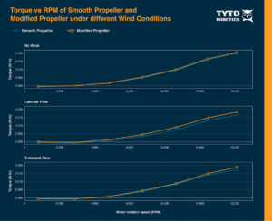
Torque required by the smooth and modified propellers under each wind condition
In the absence of wind, both propellers required nearly identical torque across much of the tested rotational speed range.
Under laminar flow, however, the modified propeller required progressively greater torque as RPM increased. This condition produced the largest torque difference between the two designs.
At approximately 11,700 RPM, the modified propeller required 3.7% additional torque with no wind, 11.2% additional torque under the laminar flow condition, and 7.9% additional torque under the turbulent flow condition.
The increased torque requirement may be associated with additional aerodynamic drag introduced by the vortex generators.
If the raised features increase resistance to blade rotation, the propulsion system requires more torque to maintain a given rotational speed.
However, torque measurements alone do not establish how effectively the propeller converts the supplied power into useful thrust.
Effects on Overall Thrust Efficiency
The efficiency comparison considered the amount of thrust generated relative to the electrical power supplied to the system.
Measurements below 2,000 RPM were excluded from the displayed efficiency comparison to make differences at higher speeds easier to distinguish, although these measurements remained in the recorded dataset.
At very low rotational speeds, both thrust and power approach zero. Consequently, small measurement variations can produce disproportionately large changes in calculated efficiency, making results in this region less reliable for comparison.
Across much of the operating range, the smooth and modified propellers exhibited broadly similar efficiency trends, but the modified configuration became less efficient at higher rotational speeds.
At approximately 11,700 RPM, the recorded efficiency differences were 9.2% lower under no-wind conditions, 11.1% lower under laminar flow, and 14.9% lower under turbulent flow.
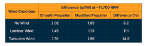
Under no-wind conditions, the efficiency of both propellers remained relatively close throughout most of the operating range, with the modified propeller becoming less efficient as rotational speed increased.
A similar pattern emerged under laminar flow. The two efficiency curves remained comparatively close through much of the normal operating range, although the modified configuration showed a greater disadvantage at higher RPM.
Under turbulent flow, the efficiency penalty was more pronounced, particularly at lower rotational speeds.
The difference decreased as RPM increased, with the efficiency curves beginning to converge at approximately 4,500 RPM.
From around 6,500 to 12,000 RPM, efficiency remained relatively stable for both propellers under all three airflow conditions, although the smooth configuration maintained a small efficiency advantage throughout this range.
Above 10,000 RPM, the efficiency of both propellers began to decrease slightly.
Why Torque and Efficiency Followed Different Trends
The relationship between torque and efficiency helps explain the differences observed across the airflow conditions.
Increasing torque generally means the motor must use more power to maintain the same rotational speed. However, overall thrust efficiency also depends on how much thrust is produced using that power.
Under laminar flow, the modified propeller required substantially more torque, but its thrust output remained relatively close to that of the smooth configuration. As a result, the overall efficiency trends were broadly similar across much of the operating range.
Under turbulent flow, the difference in torque was smaller, but the modified propeller experienced a greater reduction in thrust.
Consequently, the modified propeller produced less useful thrust relative to the power consumed, resulting in the largest measured efficiency deficit at approximately 11,700 RPM.
Taken together, the findings did not support the initial hypothesis.
The vortex generators did not improve overall thrust efficiency under any of the three tested airflow conditions. Instead, the modified propeller generally produced less thrust while requiring more torque at comparable rotational speeds.
Possible Reasons for the Performance Reduction
Several factors may explain why the modified propeller did not reproduce the benefits reported in the stationary airfoil research.
These potential mechanisms were not directly verified through boundary layer measurements, but they provide a basis for evaluating the surface modification and planning further experiments.
Vortex Generator Position
The hexagonal dimples used in the NACA-4415 airfoil research were associated with delayed boundary layer separation and reduced wake formation at higher angles of attack.
On the modified propeller, however, the vortex generators were positioned along the leading edge of the blades.
A blunt surface feature placed too close to the leading edge can introduce disturbances that produce additional drag or encourage premature flow separation.
Rather than improving boundary layer attachment, such features may disrupt airflow before the intended aerodynamic benefit can develop.
The effectiveness of a vortex generator therefore depends not only on its shape but also on its position relative to the location where separation would otherwise occur.
Vortex Generator Dimensions
The relative dimensions of the raised features may also have influenced the results.
On aircraft wings, vortex generators are generally small compared with the overall dimensions of the aerodynamic surface. They may be only a fraction of an inch high and a few inches long.
For comparison, the Boeing 767 uses seven vortex generators on each wing. These have a height of 19.05 mm, equivalent to approximately 0.316% of the aircraft’s 6.03 m aerodynamic chord.
The vortex generators used on the modified 4-inch propeller were 1 mm high, representing approximately 5% of the blade chord.
Although physically small, the features were substantially larger relative to the local aerodynamic surface than those in the aircraft example.
This comparatively large size may have introduced excessive airflow disturbance and drag, offsetting any potential benefit from delayed separation.
Varying Airspeed and Blade Geometry
Unlike a stationary airfoil exposed to a comparatively uniform incoming airflow, a propeller operates with significant changes in local velocity along the blade.
The blade tip moves through the air at a higher rotational speed than sections closer to the hub.
Local blade angle also varies between the root and tip.
These differences affect the aerodynamic conditions experienced along the propeller and may influence where boundary layer separation occurs.
For surface modifications to be effective, their dimensions and placement may need to account for these local variations.
In the tested propeller, the vortex generators were distributed uniformly along the leading edge, without changes in height, length, or distance from the leading edge.
This arrangement did not account for differences in blade geometry and airflow conditions along the radius.
Centrifugal and Coriolis Effects
Rotating blades are also influenced by flow mechanisms that are not present in the same form on stationary airfoils.
Centrifugal effects can drive airflow outward along the blade toward the tip.
The Coriolis effect describes the apparent sideways deflection of moving air when observed from the rotating blade, resulting from the blade’s rotation and the motion of the air relative to it.
Under some conditions, these effects can contribute to improved boundary layer attachment and help delay stall, even without the addition of vortex generators.
Adding raised surface features could interfere with flow attachment already influenced by these rotational effects.
This provides another possible explanation for why an approach that produced favorable results on a stationary airfoil did not improve performance on the rotating propeller.
Refining Vortex Generator Design for Future Testing
The results suggest that further investigation should begin by identifying where boundary layer separation actually occurs on the propeller.
With this information, vortex generators could be positioned more selectively rather than distributed uniformly along the leading edge.
Two potential modifications are placing vortex generators immediately upstream of identified separation points and limiting their installation to blade regions where separation occurs.
This approach could reduce unnecessary drag in regions where the airflow already remains attached.
Additional experiments could investigate several design variables independently:
- Different angles of attack: Examining how the modified propeller behaves under changes in local aerodynamic loading.
- Alternative vane angles: Testing different orientations, including counter-rotating vortex generator pairs.
- Larger propellers: Investigating the influence of propeller dimensions on the effectiveness of surface features.
- Recessed dimples: Comparing protruding vanes with surface modifications that do not extend above the blade profile.
Vortex generator height should also be selected with reference to the dimensions of the propeller and its blade chord rather than using a uniform feature size without accounting for scale.
Manufacturing consistency represents another consideration.
Because the test propellers were 3D printed, defects or variations introduced during fabrication could affect measured performance.
Testing multiple samples of each configuration would help account for these differences and improve confidence in subsequent comparisons.
Implications for UAV Propeller Aerodynamics
The Tyto Robotics experiment demonstrates the importance of evaluating boundary layer modifications under the operating conditions of the specific aerodynamic component being tested.
Although surface features can delay airflow separation in some applications, their introduction also creates disturbances and potentially increases drag.
The balance between these effects depends on geometry, local airflow conditions, feature dimensions, and placement.
For the two 4-inch propellers examined, the modified configuration generally generated less thrust and required more torque at comparable RPM. Its overall efficiency was also lower than that of the smooth propeller under no-wind, laminar-flow, and turbulent-flow conditions.
These observations are consistent with an aerodynamic penalty associated with the raised features. However, because boundary layer transition and separation were not measured directly, the experiment does not establish which flow mechanisms caused the differences.
The findings also do not rule out potential benefits from alternative surface modifications or different vortex generator configurations.
Instead, they indicate that techniques shown to improve airflow attachment on stationary airfoils require careful assessment before being applied to rotating propeller blades.
Further testing that combines direct examination of boundary layer separation with targeted changes to feature geometry and placement could help determine whether surface modifications can improve propeller performance without introducing a greater aerodynamic penalty.
Read How Boundary Layer Behaviour Shapes Propeller Performance on the Tyto Robotics website.