


To provide Vertiq’s partners and those interested in its drone propulsion modules with the most relevant data, the company conducts and shares comprehensive thrust testing data using various third-party propellers.
The first step involves determining which propeller sizes to test and publish for each specific module. Leveraging previous testing data, Vertiq has developed an internal program that simulates propeller performance on its motor modules at different supply voltages, streamlining this process.
Drone propellers that are too large for a module will reach the pre-determined continuous torque limit at low speeds and low commanded voltages. Conversely, propellers that are too small will hit the maximum commanded voltage and velocity without producing significant thrust or approaching the continuous torque limit.
Preparing the Test Stand
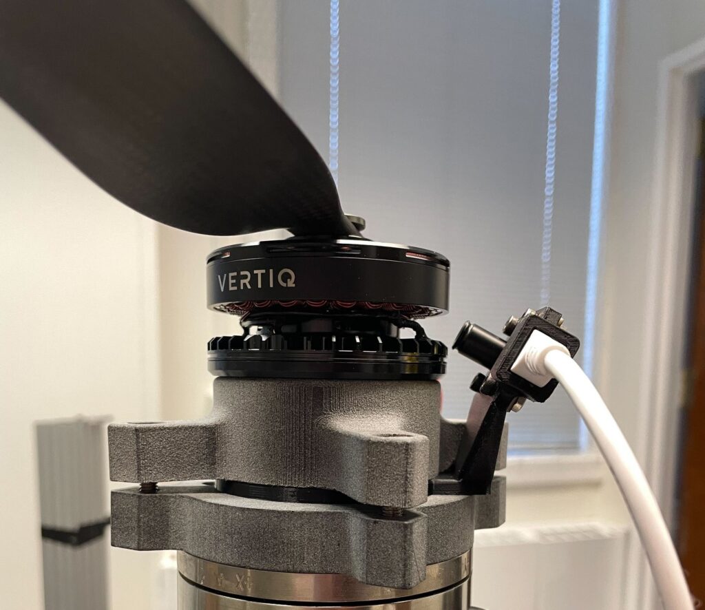
After identifying the appropriate range of propeller sizes for a specific motor module, Vertiq prepares the test using its internally developed thrust test stand. The motor/ESC module is mounted onto an ATI Mini85 Force/Torque (F/T) sensor.
Since this sensor is sensitive to temperature changes, the module is not mounted directly onto the sensor or onto thermally conductive materials that might transfer heat from the motor/ESC to the sensor.
Instead, Vertiq attaches the module to a thick nylon mounting plate positioned between the module and the sensor. This non-conductive material protects the F/T sensor from extreme temperature fluctuations and ensures the integrity of the collected data.
By using a non-conductive surface, no additional heat sinking or cooling is introduced into the setup.
Configuring Testing Parameters
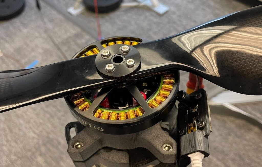
While mounting the motor module to the test stand, Vertiq also attaches a small IR sensor using a mount specifically designed for the module under test. This ensures the IR sensor barrel is aimed directly at one of the coils.
Coil temperature data collected during testing is used to fine-tune Vertiq’s coil temperature estimator model. Although this precise temperature data is not published on the website, it provides valuable insights during testing with different propellers.
Environmental conditions in the testing room, including temperature, pressure, and humidity, are also monitored and recorded at the top of all published data. All data is fed into a National Instruments DAQ system.
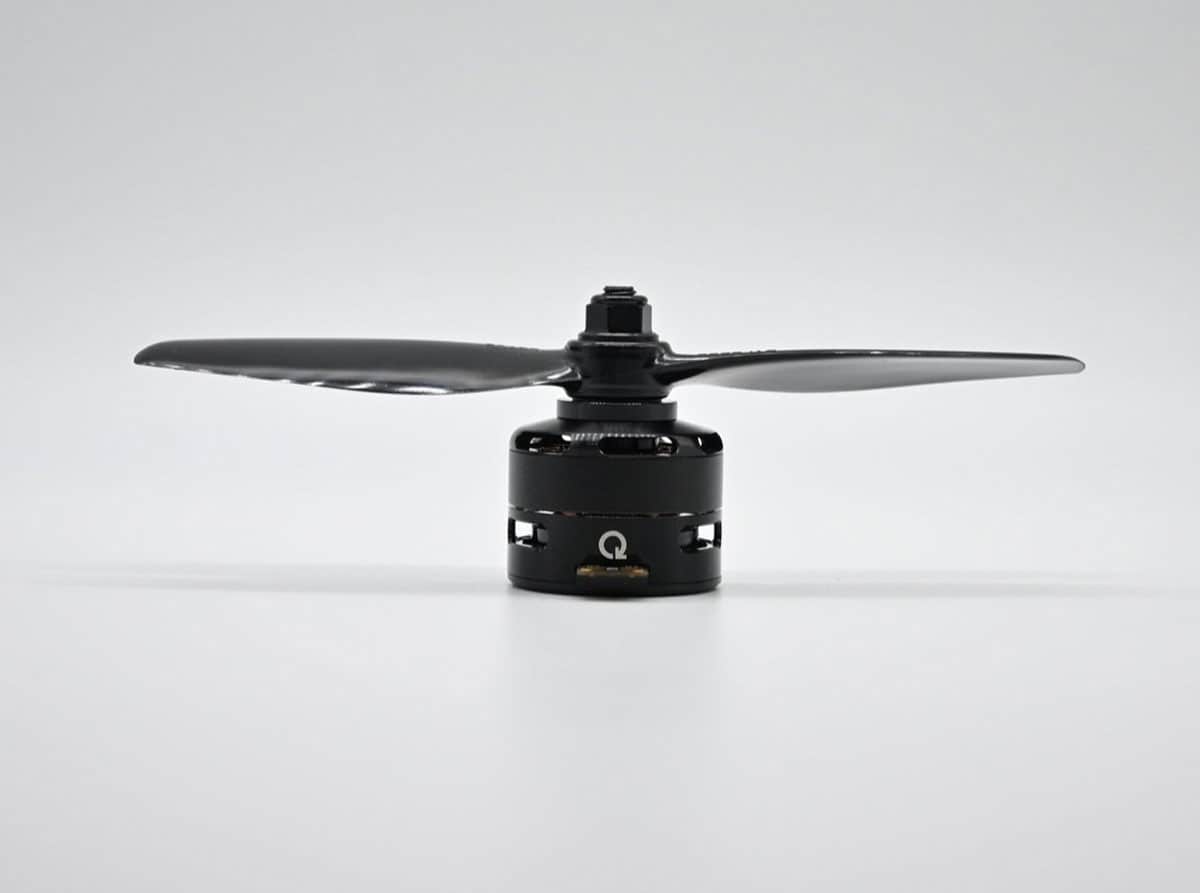
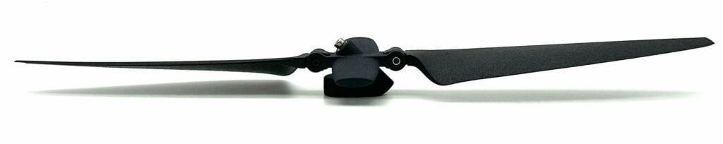
Once the motor module and IR sensor are properly mounted, the first propeller is attached using the correct adapters. Power supplies are then configured to the appropriate voltage for the upcoming test.
Larger propellers typically require lower voltage since they reach the continuous torque limit at lower velocities. Smaller propellers, on the other hand, are tested at the highest recommended operating voltage for the module to achieve maximum speed during testing.
Gathering & Analyzing Thrust Data
For instance, when testing a 28-inch propeller on Vertiq’s 60-08 150Kv G2 Module, 24V was supplied. When testing a 20-inch propeller on the same module, 48V was supplied.
In both cases, the module reached its continuous torque limit of 1.05Nm but at different commanded voltage steps and velocities. There was no need to supply 48V during the 28-inch propeller test since the module hit its continuous torque limit around 22V commanded voltage.
Test steps where the motor module is pushed beyond its continuous torque limit are not published. Although these values can be achieved, they are not sustainable for practical use without the module derating to prevent overheating and potential damage.
Once power and communication are connected to the motor module, testing begins. Using Voltage Mode and IQUART for communication, the commanded voltage is increased incrementally—typically by 1 or 2V—from 0V to the supply voltage. At each step, the motor is run long enough to collect smooth and consistent data.
At the conclusion of the test—whether at maximum commanded voltage or derating beyond the continuous torque limit—a steady-state test is conducted. This continuous portion collects the Convection Thermal Conductivity Coefficient for the specific propeller and motor module combination.
This coefficient enhances the accuracy of Vertiq’s internal coil temperature estimator model, which requires adjustments for different propellers due to their varying airflow and cooling effects.
The coefficient, along with velocity feedforward values collected during the voltage sweep, is included in the default configuration files on IQ Control Center. Thanks to this pre-collected data, users can simply select their propeller, and these otherwise challenging values will auto-populate for them.
Results & Ongoing Testing
Currently, Vertiq has approximately 100 different propeller thrust tests for its various motor/ESC options published on its website. As new modules are developed and released, this number will continue to grow. If there is a specific propeller and module combination you would like tested, get in contact with Vertiq.