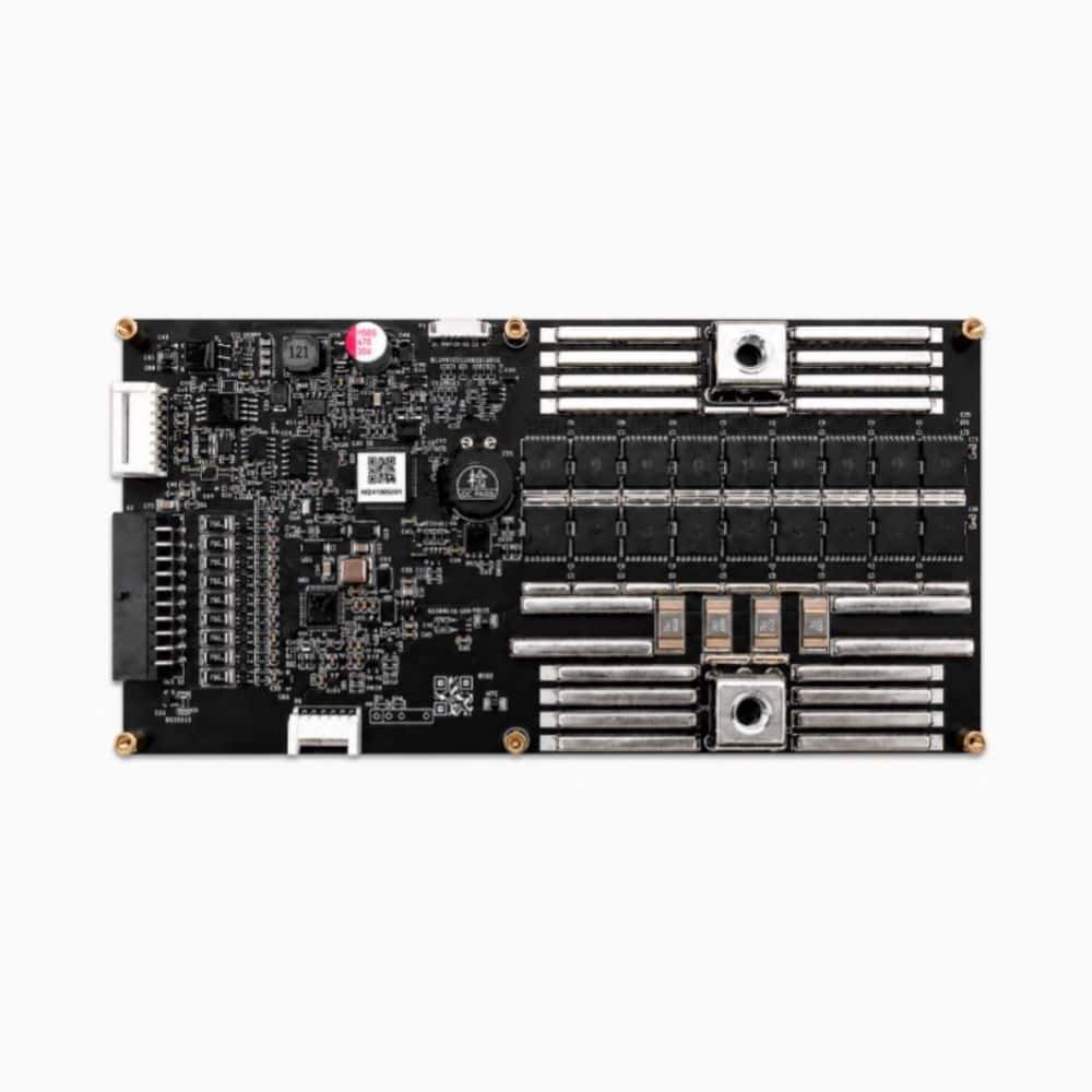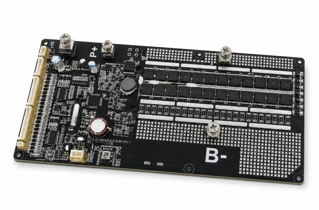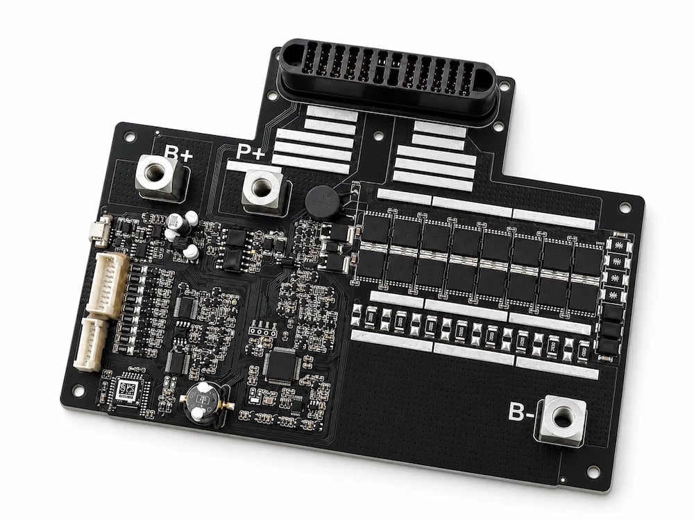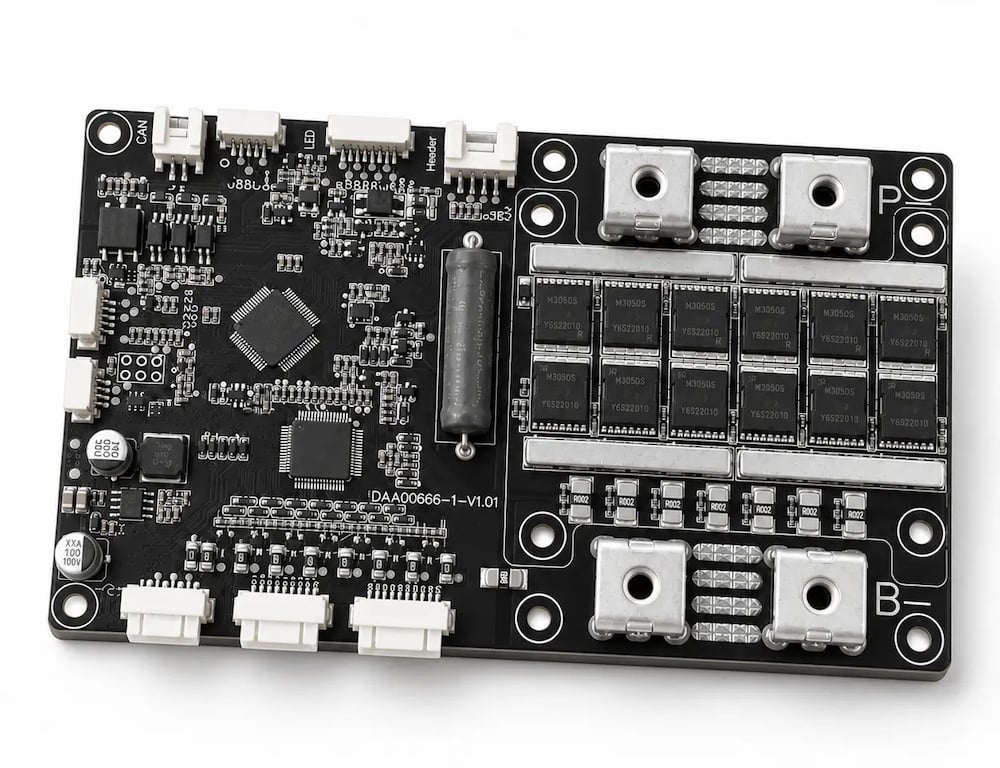



AYAATECH explores how integrating Battery Management Systems (BMS) with UAV flight systems through DroneCAN and Cyphal interfaces can improve battery monitoring, data reliability, and power management for industrial unmanned aircraft.
In many industrial Unmanned Aerial Vehicles (UAVs), battery telemetry still amounts to pack voltage. The reading is useful, but it cannot describe by itself how much energy will be available for the next part of a mission. Current draw, temperature, cell condition, and the point on the discharge curve all affect the result.
That matters when the aircraft moves between loads. A pack can look acceptable during a low-power leg and then sag during take-off, a climb, or payload release. It can also behave differently in cold air from an equally charged pack at its intended operating temperature.
An integrated BMS gives flight and ground software a broader view of the power system. It can report what the pack is doing now, how much usable charge remains, whether temperature is becoming a limit, and whether it has detected a fault. The BMS does not fly the aircraft. The flight controller and the aircraft’s validated safety logic must decide how the vehicle responds.
Voltage is Not Enough
Pack voltage is easy to measure, but it is an imperfect indication of remaining flight time. The same reading can imply different usable energy when current demand, temperature, pack age, or internal resistance changes. A voltage sag under high load may recover after the load falls, so an isolated reading can be misleading.
For an industrial mission, the useful question is whether the pack has margin for the next flight segment. A battery that is adequate for a mapping leg may not have enough reserve for a climb, payload release, or return-to-home segment. A pack operating close to a temperature limit may need a different operational decision from one with the same state of charge that is operating within range.
The aircraft manufacturer should therefore specify the small set of battery values it needs, how current those values must be, and what they mean across every pack used on the platform.
The BMS Data Set
A BMS monitors cells and pack-level conditions, then publishes selected information through a communication interface. A UAV integration will commonly use the following data:
- Pack voltage and current, which show the electrical state at the pack terminals and the present load.
- State of charge (SOC), an estimate of usable charge remaining. SOC quality depends on the BMS design, current measurement, battery model, and calibration.
- State of health (SOH), an estimate of pack ageing relative to its intended condition. It can support maintenance planning, but it does not replace a pre-flight check.
- Temperature data from the pack, cell area, and/or electronics where the BMS supports those measurements.
- Cell-level voltage or imbalance information when the BMS and protocol expose it.
- Status and fault flags, such as active protection events, sensor errors, communication faults, or data that is no longer valid.
The aircraft manufacturer should define the exact data set. The flight controller needs consistent units, validity rules, and update rates. If a value is unavailable or stale, the system should report that state rather than display it as a live measurement.
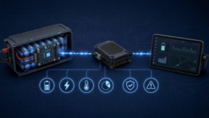
DroneCAN and Cyphal Require Separate Integration Work
DroneCAN and Cyphal are often mentioned together in UAV power discussions, but an engineering team should not treat them as interchangeable. DroneCAN is an open protocol ecosystem based on the earlier UAVCAN v0 specification and is widely used on CAN-based unmanned systems. Cyphal evolved from UAVCAN v1. It is a separate protocol family for distributed real-time systems and can use transports such as CAN FD and UDP/IP.
Their messages, data types, transport assumptions, and software support are not automatically wire-compatible. A BMS that supports one ecosystem does not necessarily communicate with a flight controller configured for the other.
Before selecting the BMS interface, the team should confirm:
- The protocol version and transport required by the flight-control stack.
- The battery-status message or data type the controller expects.
- The fields, units, update rates, and error flags that must be delivered.
- How node allocation, configuration, firmware updates, and device diagnostics will work in production and service.
- Resolving those points early avoids a familiar problem: a battery that fits the aircraft electrically but cannot deliver usable telemetry to its software.
Using Battery Telemetry in the Aircraft
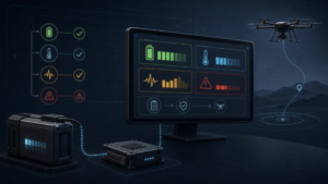
The data path is simple in concept. The BMS measures battery conditions, publishes defined messages on the CAN bus, and the flight controller or a power-management node receives them. The ground-control station can then display the relevant values and mission logs can record them.
The value comes from the logic built around that path. Several common cases illustrate the point:
- Pre-flight readiness checks can confirm that the selected pack is present, suitable for service, within its permitted temperature range, and reporting valid data before arming.
- During a high-current take-off, voltage, current, and temperature trends can help distinguish a normal short peak from a condition that deserves a warning or post-flight investigation.
- In cold-weather operations, battery temperature and charge-acceptance limits can show whether a pack needs conditioning before use. A nominal SOC alone cannot answer that question.
- A validated energy model can combine battery telemetry with vehicle consumption to present a more meaningful return margin than voltage alone.
- If expected BMS messages stop arriving, the vehicle should show that the data is stale. It should not continue to display the last value as if it were live.
The BMS may report a warning, a thermal limit, or a fault state. The aircraft manufacturer defines the response through the flight controller, operator interface, and operating procedures. Clear ownership matters because the BMS, flight controller, payload system, and ground-control software must not issue conflicting commands.
Building a Dependable Telemetry Path
Define the interface
Document the message set, units, scaling, valid ranges, update rates, and timeout behaviour. Include the status of each measurement, not just its value. For example, the team should define what 100% and 0% SOC mean for the specific pack and operating policy.
Design the CAN bus with the aircraft
CAN wiring, connector selection, termination, grounding strategy, electromagnetic compatibility, and node identification all affect communication reliability. Review these details with the battery enclosure and high-current wiring, not during final integration.
Make data freshness visible
A valid measurement received one second ago and the same measurement received twenty minutes ago are different conditions. The telemetry consumer should detect late or missing messages and distinguish a communication failure from a genuine battery reading.
Keep warning and control authority separate
The platform must define which subsystem owns each response to a BMS alarm or protection state. This prevents conflicts between the BMS, flight controller, payload system, and ground-control software.
Test the full chain
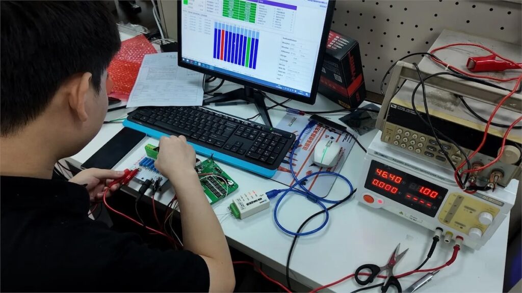
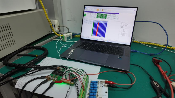
Bench testing should compare reported voltage, current, temperature, and status against controlled measurements. Integration testing should then cover start-up, arming, high-load profiles, message timeouts, reconnect behaviour, and data logging in representative operating conditions.
Checklist for UAV OEMs
Before releasing a smart-battery integration to production, a UAV OEM should be able to answer the following questions:
- Does the BMS use the DroneCAN or Cyphal path required by the flight-control architecture?
- Are battery-status fields, units, freshness requirements, and fault flags documented and tested?
- Does the CAN network have the correct wiring, termination, node management, and diagnostics?
- Is SOC useful across the intended current, temperature, and pack-age range?
- What does the vehicle display when battery data or BMS communication is unavailable?
- Which subsystem owns warnings, power limitations, return-margin calculations, and operator instructions?
- Have bench, integration, and representative flight tests shown that recorded data matches battery behaviour?
This checklist does not replace an aircraft safety assessment. It gives the battery, avionics, and software teams a shared basis for defining what the power system must report and how the vehicle should respond.
A networked smart battery gives the aircraft more useful information than a voltage-only pack. The benefit depends on defined data, a protocol path that the flight-control stack supports, and validation of the full data chain in representative conditions.
Where a standard interface does not meet the platform’s requirements, a custom UAV BMS development programme can define the pack configuration, current profile, telemetry interface, and validation work around the aircraft. The aim is to give the flight system credible power information before it needs to make a time-critical decision.