Southwest Antennas

High Performance RF & Microwave Antennas for UAVs, Robotics, USVs and Unmanned Marine Vehicles

United States of America
Southwest Antennas
High Performance RF & Microwave Antennas for UAVs, Robotics, USVs and Unmanned Marine Vehicles
12305 Crosthwaite Cir, Poway, CA 92064 United States of America Regional offices
+1 (858) 247-0671

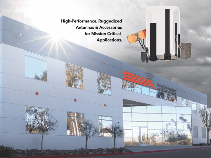
Southwest Antennas is a leading designer and manufacturer of high-performance RF antennas, microwave antennas and accessory products for military, defense, law enforcement, homeland security, broadcast video, and other commercial applications. Founded in 2005, our products are manufactured in San Diego, California.

MTS Antenna
Southwest Antennas MIMO / MANET sector antenna on AVwatch MTS auto-tracking system

Our RF antennas and microwave antennas are deployed on unmanned and autonomous systems both domestically and internationally, and can be found on ground control stations, handheld controllers and video receivers, unmanned aerial vehicles (UAVs), unmanned ground vehicles (UGVs), and unmanned marine systems.

All Southwest Antennas products are radio agnostic and can be used with almost all SISO or MIMO / MANET radio systems on the market today. Additionally, we’ve designed specifically for tactical radio systems and multi-port MIMO/MANET systems.

antenna in anechoic chamber

Iridium & GPS L1 Antenna

Location Service and SATCOM Antenna

Iridium & GPS L1 SATCOM AntennaThis lightweight and compact hemispherical passive antenna is designed for use on the Iridium worldwide satellite communication and location service network.  Providing both transmission and reception, it enables two-way voice and data communication from anywhere in the world.

The antenna also supports GPS L1, providing timing and location for any attached radio system that supports GPS reception. It has been designed with a wide 120-degree hemispherical coverage area to capture as much sky as possible and reduce satellite acquisition time.

Part # Frequency Ranges Total Peak Gain Horizontal Beamwidth Low Band Vertical Beamwidth High Band Vertical Beamwidth
1027-035 1.565 – 1.585 GHz
1.616 – 1.627 GHz
2.3 dBic 360 degrees 120 degrees TNC(m) Non-Rotating

GNSS Active Antenna

Rugged GPS & GLONASS L1/L2 patch antennaSouthwest Antennas GPS & GLONASS patch antenna

Our GPS & GLONASS Active L1/L2 patch antenna is ideal for commercial, industrial and tactical military unmanned systems PNT (position, timing, and navigation) applications.

Featuring a built-in LNA (low-noise amplifier) and filtering, it provides high performance even in contested and congested RF environments.

The low-profile radome gives it a minimal footprint, and the custom black chrome SMA(f) RF connector provides waterproofing and allows users to fully customize cable length and type for mounting locations away from the receiver. An innovative magnetic mount, integrated flush into the radome, provides quick securing to and removal from any ferromagnetic surface.

Part # Frequency Ranges Total Peak Gain Horizontal Beamwidth Low Band Vertical Beamwidth High Band Vertical Beamwidth
1065-042 1.217 – 1.238 GHz
1.565 – 1.586 GHz
+28 dB 360 degrees 120 degrees (L2) 100 degrees (L1)

Horizontally Polarized Directional Patch Antenna

Small form factor L- and S-band antenna

Horizontally Polarized Directional Patch Antenna

This directional patch antenna, designed for L- and S-band applications, provides horizontal polarization when installed with the RF connector facing down, and can also be deployed for vertical polarization requirements.

With a frequency range of 1.7 – 2.5 GHz, it is ideal for a wide variety of unmanned systems communication needs in defense, law enforcement and 2.4 GHz ISM applications. It can also be used to facilitate MIMO and MANET mesh networks for drones and robotics.

Part # Frequency Ranges Maximum Gain Horizontal Beamwidth Vertical Beamwidth Frequency Bandwidth
1004-034 1.7 – 2.5 GHz 9.8 dBi 61 – 73 degrees 54 – 62 degrees 800 MHz

Half-Wave Dipole Omni-Antenna

Half-Wave Dipole Omni-Antenna

Low-SWaP C-band antenna

This rugged small form factor omni-directional antenna covers the 4.4 – 5.9 GHz frequency range with 3.2 dBi of peak gain. It features an integrated strain relief spring, covered by a weatherproof heatshrink seal, protecting the RF connector and attached system from damage.

The rugged construction and small, lightweight form factor make it ideal for space- or weight-constrained UAVs and UGVs.

Part # Frequency Ranges Maximum Gain Horizontal Beamwidth Vertical Beamwidth Frequency Bandwidth
1001-256 4.4 – 5.9 GHz 3.2 dBi 360 degrees 47-65 degrees 1.5 GHz

Ultra-Flex Omni-Directional Antennas

Compact, rugged omni-directional sector antennas, with integrated environmentally sealed spring base

Ultra-Flex Omni-Directional AntennasOur line of Ultra-Flex Omni Antennas are designed to offer high-performance communication in a small package, ideal for unmanned ground systems. Featuring an integrated sealed spring base which can bend ±90 degrees from vertical, reduces the risk of damage to the antenna or mated radio RF connector if the antenna is struck by another object. This feature is especially well-suited to ground robotics platforms which may encounter low-hanging obstacles while in operation.

Our Ultra-Flex are also deployed on UAV systems with the ground clearance and payload capacity to support external antennas.

Available from 902 MHz to 6,000 MHz in a variety of band and RF connector options. Our Ultra-Flex antennas are also waterproof to 20 meters when mated to a waterproof RF connector.

ugv-antenna
Southwest Antennas omni-directional antenna and magnetic mounting kit utilized on a MUTT unmanned vehicle at Marine Corps Base Camp Pendleton, California. Photo: John F. Williams, US Navy
Omni-directional antennas for UGVs
Images courtesy of Carnegie Robotics.
Ultra-flex omni-directional-antenna-on-vehicle-with-uav

Specifications

SWA Part # Min. Freq (MHz) Max. Freq (MHz) Gain (dBi) RF Connector
1001-171 902 928 2.15 TNC(m), Non-Rotating
1001-232 902 928 2.15 SMA(m), Non-Rotating
1001-237 902 928 2.15 Type-N(m), Non-Rotating
1001-130 1000 1500 2.15 TNC(m), Non-Rotating
1001-174 1000 1500 2.15 Type-N(m), Non-Rotating
1001-210 1000 1500 2.15 TNC(f)
1001-154 1250 1850 2.05 TNC(m), Non-Rotating
1001-109 1350 1400 2.15 RP-TNC(m), Non-Rotating
1001-110 1350 1400 2.15 TNC(m), Non-Rotating
1001-111 1350 1400 2.15 SMA(m), Non-Rotating
1001-112 1350 1400 2.15 RP-SMA(m), Non-Rotating
1001-136 1625 2110 2.15 TNC(m), Non-Rotating
1001-068 2100 2500 2.15 SMA(m), Non-Rotating
1001-069 2100 2500 2.15 RP-SMA(m), Non-Rotating
1001-070 2100 2500 2.2 Type-N(m), Non-Rotating
1001-085 2100 2500 2.15 TNC(m), Non-Rotating
1001-107 2100 2500 2.15 RP-TNC(m), Non-Rotating
1001-236 2500 2700 2.0 Type-N(m), Non-Rotating
1001-126 4400 6000 2.3 TNC(m), Non-Rotating
1001-175 4400 6000 2.3 RP-TNC(m), Non-Rotating
1001-200 4400 5900 3.5 RP-TNC(m), Non-Rotating
1001-062 5000 6000 2.3 SMA(m), Non-Rotating
1001-063 5000 6000 2.3 RP-SMA(m), Non-Rotating
1001-065 5000 6000 2.3 Type-N(m), Non-Rotating
1001-084 5000 6000 2.3 RP-TNC(m), Non-Rotating
1001-086 5000 6000 2.3 TNC(m), Non-Rotating
1001-215 5000 6000 2.3 Type-N(m), Non-Rotating
1001-216 1000 1500 2.15 SMA(m), Non-Rotating
SWA Part # Min. Freq (MHz) Max. Freq (MHz) Gain (dBi) RF Connector
1001-103 2100 – 2500 4400 – 5900 2.5 SMA(m), Non-Rotating
1001-104 2100 – 2500 4400 – 5900 2.5 TNC(m), Non-Rotating
1001-124 2100 – 2500 4400 – 5900 2.5 Type-N(f)
1001-142 2100 – 2500 4400 – 5900 2.5 Type-N(m), Non-Rotating

Gooseneck Omni-Directional Antennas

Versatile RF antennas and microwave antennas with integrated, flexible coaxial gooseneck base

RF Gooseneck antennasOur line of gooseneck omni-directional sector antennas are widely deployed on unmanned ground systems, handheld control units, tactical radio systems, and ground control stations.

The integrated RF coaxial gooseneck base allows the RF antenna to bend and hold non-vertical angles, which is particularly important on handheld controllers or other radio systems that are not resting on a flat vertical surface.

Custom slant angles can also be deployed when used in MIMO and MANET mesh radio systems, delivering enhanced polarization and spatial diversity, especially in environments where multipath propagation can be utilized.

Specifications

SWA Part # Min. Freq (MHz) Max. Freq (MHz) Gain (dBi) RF Connector
1001-207 698 970 2.07 TNC(m) Non-Rotating
1001-340 698 970 2.0 Type-N(m) Non-Rotating
1001-148 700 970 2.07 TNC(m) Non-Rotating
1001-094 902 928 2.15 TNC(m) Non-Rotating
1001-087 969 1206 2.15 TNC(m) Non-Rotating
1001-164 969 1206 2.15 TNC(m) Non-Rotating
1001-081 1000 1500 2.15 SMA(m) Non-Rotating
1001-095 1000 1500 2.1 RP-TNC(m) Non-Rotating
1001-217 1000 1500 2.1 TNC(m) Non-Rotating
1001-149 1250 1850 2.05 TNC(m) Non-Rotating
1001-113 1350 1400 2.15 RP-TNC(m) Non-Rotating
1001-114 1350 1400 2.15 TNC(m) Non-Rotating
1001-115 1350 1400 2.15 SMA(m) Non-Rotating
1001-116 1350 1400 2.15 RP-SMA(m) Non-Rotating
1001-097 1625 2110 2.15 SMA(m) Non-Rotating
1001-135 1625 2110 2.15 TNC(m) Non-Rotating
1001-138 1700 1900 2.1 TNC(m) Non-Rotating
1001-192 1700 2500 2.0 Type-N(m) Non-Rotating
1001-193 1700 2500 2.0 SMA(m) Non-Rotating
1001-161 1755 2270 2.1 TNC(m) Non-Rotating
1001-177 1755 2270 2.1 SMA(m) Non-Rotating
1001-180 1775 2270 4.0 TNC(m) Non-Rotating
1001-150 1850 2600 1.74 TNC(m) Non-Rotating
1001-159 1850 2600 2.45 SMA(m) Non-Rotating
1001-074 1980 2200 2.2 SMA(m) Non-Rotating
1001-123 1980 2200 2.2 TNC(m) Non-Rotating
1001-184 1980 2200 2.2 RP-TNC(m) Non-Rotating
1001-233 1980 2700 2 TNC(m) Non-Rotating
1001-052 2100 2500 2.15 SMA(m) Non-Rotating
1001-089 2100 2500 2.15 RP-SMA(m) Non-Rotating
1001-105 2100 2500 2.15 TNC(m) Non-Rotating
1001-108 2100 2500 2.15 RP-TNC(m)
1001-204 2100 2500 2.15 Type-N(m) Non-Rotating
1001-053 4000 8000 2.15 SMA(m)
1001-076 4000 8000 2.15 SMA(m) Non-Rotating
1001-101 4000 8000 2.15 RP-TNC(m)
1001-128 4000 8000 2.15 TNC(m)
1001-140 4400 5900 3.5 TNC(m)
1001-186 4400 5900 3.5 RP-TNC(m)
SWA Part # Min. Freq (MHz) Max. Freq (MHz) Gain (dBi) RF Connector
1001-103 2100 – 2500 4400 – 5900 2.5 SMA(m), Non-Rotating
1001-104 2100 – 2500 4400 – 5900 2.5 TNC(m), Non-Rotating
1001-124 2100 – 2500 4400 – 5900 2.5 Type-N(f)
1001-142 2100 – 2500 4400 – 5900 2.5 Type-N(m), Non-Rotating
SWA Part # Low Band (MHz) Mid Band (MHz) High Band (MHz) Gain (dBi) RF Connector
1001-181 1700 – 1850 2200 – 2500 4400 – 5000 2.7 TNC(m) Non-Rotating
1001-182 1700 – 1850 2200 – 2500 4400 – 5000 2.7 SMA(m) Non-Rotating
1001-183 1700 – 1850 2200 – 2500 4400 – 5000 2.7 Type-N(m) Non-Rotating
1001-238 1700 – 1850 2200 – 2500 4400 – 5000 2.7 SMA(m) Non-Rotating

Cylindrical Sector Antennas

Sector antennas housed in a compact, cylindrical radome

Cylindrical Sector AntennasOur cylindrical sector antennas are ideal for use on base stations for control and communication with aircraft at a distance or near the horizon, and are often deployed with other omni-directional antennas.

These directional sector antennas are housed in a compact, cylindrical radome which makes them easy to transport and set up. An arrow on the top of the radome denotes signal transmission and reception direction.

Specifications

SWA Part # Min. Freq (MHz) Max. Freq (MHz) Gain (dBi) RF Connector
1034-005 2025 2070 12 Type-N(f)
1034-006 2100 2500 12 TNC(m)
1034-002 2200 2500 12 TNC(m)
1034-003 2200 2500 12 Type-N(m)
1034-009 2200 2500 12 TNC(m)
1034-008 4400 5300 12 Type-N(m)
1034-001 4400 5300 12 TNC(m)

More Information: Cylindrical Sector Antennas

Multi-Port MIMO/MANET

Omni-directional slant antennas designed for multi-port MIMO / MANET radio systems

Multi-Port MIMO:MANET Omni-Directional AntennasOmni-directional antennas engineered specifically for use with multi-port MIMO / MANET radio systems.

Featuring slant left and slant right polarization, improving polarization diversity and performance in high multipath environments, while a variety of mounting options and choice of two or four ports provides operational flexibility.

Suitable for unmanned and autonomous ground systems, base stations, fixed site infrastructure, or for use on larger UAV systems.

MIMO/MANET Omni-Directional Antennas for UAS
Image courtesy of NASC and NASA.

Specifications

Part # Min Freq Max Freq Maximum Gain (dBi) Connector Type Polarization Special Features
1055-267 2100 2500 2.9 2x Type-N(f) 45° Slant Left/Right
1055-274 2100 2500 3.0 4x Type-N(f) 45° Slant Left/Right
1055-278 2100 2500 2.9 2x SMA(f) 45° Slant Left/Right
1055-301 2100 2500 2.9 2x Type-N(m) 45° Slant Left/Right Magnetic base and integrated RF cable
1055-302 2100 2500 3.0 4x Type-N(m) 45° Slant Left/Right Magnetic base and integrated RF cable
1055-321 2100 2500 2.9 2x Type-N(f) 45° Slant Left/Right
1055-325 4400 5000 2.6 4x Type-N(f) 45° Slant Left/Right
1055-326 4400 5000 2.6 2x Type-N(f) 45° Slant Left/Right
1055-347 4400 5000 2.9 2x Type-N(m) 45° Slant Left/Right Magnetic base and integrated RF cable
1055-348 2100 2500 2.9 2x SMA(f) 45° Slant Left/Right
1055-361 4400 5000 2.9 2x TNC(m) 45° Slant Left/Right Magnetic base and integrated RF cable
1055-362 4400 5000 3.0 2x TNC(m) 45° Slant Left/Right Magnetic base and integrated RF cable
1055-365 2100 2500 3.0 2x TNC(m) 45° Slant Left/Right Magnetic base and integrated RF cable
1055-369 4400 5000 2.6 2x SMA(f) 45° Slant Left/Right
1055-371 2100 2500 2.9 2x TNC(m) 45° Slant Left/Right Magnetic base and integrated RF cable
1055-377 2100 2500 3.9 2x Type-N(f) 45° Slant Left/Right Flange for aircraft mounting
1055-378 4400 5000 5.3 2x Type-N(f) 45° Slant Left/Right Flange for aircraft mounting
1055-394 4400 5000 2.6 2x SMA(f) 45° Slant Left/Right

Multi-Port MIMO / MANET Directional Sector Antennas

Single-band multi-port antennas for MIMO / MANET radio systems

Multi-Port MIMO : MANET Directional Sector AntennasOur single-band multi-port sector antennas allow for focused sectorial area coverage with MIMO and MANET systems.

Ideal for ground control systems or other fixed site infrastructure, they are available with beamwidths from 60° – 120°, and in two, three, or four port variants.

Dual-band multi-port antennas for MIMO / MANET radio systems

Southwest Antennas dual-band sector antennasWe also provide dual-band sector antennas, with an innovative design that allows for many advanced features, such as rapid band-switching for anti-jamming applications, or separating network traffic by band based on environmental operating conditions.

They feature a choice of 90 or 120 degree sectorial coverage for smaller or larger operating areas, with L/C or S/C band options. Several can be deployed together for complete 360 degree area coverage, and the included mounting kits with adjustable downtilt allow permanent installation on buildings or communication towers.

UAV Directional Sector Antenna
UAV Directional Sector Antenna 2

Specifications

Part # Min Freq (MHz) Max Freq (MHz) Maximum Gain (dBi) Connector Type Azimuth Beamwidth Polarization
1055-333 1250 2000 9.7 4x Type-N(f) 63° 45° Slant Left/Right
1055-330 1250 2000 9.4 3x Type-N(f) 67° 45° Slant Left/Right + Vertical
1055-338 1400 1700 9.8 4x Type-N(f) 64° 45° Slant Left/Right
1009-032 1700 1900 16 2x Type-N(f) 90° 45° Slant Left/Right
1009-033 1700 1900 16 2x Type-N(f) 90° 45° Slant Left/Right
1055-334 1700 2500 9.8 4x Type-N(f) 64° 45° Slant Left/Right
1055-327 1700 2500 9.7 3x Type-N(f) 67° 45° Slant Left/Right + Vertical
1055-368 1700 2500 9 2x Type-N(f) 73° 45° Slant Left/Right
1055-266 2100 2500 10.3 4x Type-N(f) 60° 45° Slant Left/Right
1055-315 2100 2500 10 3x Type-N(f) 60° 45° Slant Left/Right + Vertical
1055-381 2100 2500 10 3x Type-N(f) 60° 45° Slant Left/Right + Vertical
1055-390 2100 2500 10 3x Type-N(f) 60° 45° Slant Left/Right + Vertical
1055-346 2200 2300 10 2x TNC(f) 56° 45° Slant Left/Right
1009-024 2200 2500 15 4x Type-N(f) 90° 45° Slant Left/Right
1009-025 2200 2500 15 2x Type-N(f) 90° 45° Slant Left/Right
1009-034 2200 2500 12 4x Type-N(f) 120° 45° Slant Left/Right
1009-035 2200 2500 12 2x Type-N(f) 120° 45° Slant Left/Right
1009-047 2200 2500 12 3x Type-N(f) 120° 45° Slant Left/Right + Vertical
1055-345 4400 5000 10 2x TNC(f) 56° 45° Slant Left/Right
1055-395 4400 5000 9.3 3x TNC(f) 60° 45° Slant Left/Right
1009-062 4400 5000 16 4x Type-N(f) 90° 45° Slant Left/Right
1009-026 4400 5000 16 4x Type-N(f) 90° 45° Slant Left/Right
1009-027 4400 5000 16 2x Type-N(f) 90° 45° Slant Left/Right
1009-036 4400 5000 12 4x Type-N(f) 120° 45° Slant Left/Right
1009-037 4400 5000 12 2x Type-N(f) 120° 45° Slant Left/Right
1009-038 4400 5000 12 3x Type-N(f) 120° 45° Slant Left/Right + Vertical
Part # Band 1 (Ghz) Band 2 (Ghz) Maximum Gain (dBi) Connector Type Azimuth Beamwidth Polarization
1009-064 2.2-2.5 5.725-5.875 13 2x Type-N(f) 90° 45° Slant Left/Right
1009-065 1.35-1.40 4.4-5.0 13.7 2x Type-N(f) 90° 45° Slant Left/Right
1009-066 2.2-2.5 5.725-5.875 10.2 2x Type-N(f) 120° 45° Slant Left/Right
1009-067 1.35-1.40 4.4-5.0 12.0 2x Type-N(f) 120° 45° Slant Left/Right

Concealment Antennas

L, S and C-band antennas for embedded applications

Our compact, lightweight concealment antennas are ideal for UAV and unmanned systems designs where the antenna must be completely integrated inside the vehicle due to risk of damage during motion.

All concealment antennas can be tuned to optimize performance once located inside specific enclosures.

omni concealment antenna
1066-098
concealment antenna
1066-100

Specifications

SWA Part # Coverage Max Gain (dBi) Connector Type Polarization
1066-098 2.1 – 2.5 GHz
4.4 – 5.0 GHz
2.2 Right Angle SMP(f) Vertical
1066-100 1.35 – 1.4 GHz 1.7 Right Angle SMP(f) Vertical

More Information: Concealment Antennas

RF Filter Modules

Improve radio system performance and simplify installation

filter-modulesSouthwest Antennas offers a wide range of RF filter options for environments where interference from nearby transmitters may be causing issues for vehicles or control systems.

Our line of compact and robust RF filters allow for all-weather operation. These RF filters are bi-directional and can be installed in either direction.

RF Filter Module Specifications

Part # Description RF Connector 1 RF Connector 2 RF Power (Peak)
1080-099 Bandpass Filter, 902 – 928 MHz, In-Line SMA(m) SMA(f) 10W
1080-100 Bandpass Filter, 902 – 928 MHz, In-Line RP-SMA(m) RP-SMA(f) 10W
1080-101 Bandpass Filter, 902 – 928 MHz, In-Line TNC(m) TNC(f) 10W
1080-102 Bandpass Filter, 902 – 928 MHz, In-Line RP-TNC(m) RP-TNC(f) 10W
1080-104 Bandpass Filter, 1.35 – 1.40 GHz, In-Line SMA(m) SMA(f) 10W
1080-105 Bandpass Filter, 1.35 – 1.40 GHz, In-Line RP-SMA(m) RP-SMA(f) 10W
1080-106 Bandpass Filter, 1.35 – 1.40 GHz, In-Line TNC(m) TNC(f) 10W
1080-107 Bandpass Filter, 1.35 – 1.40 GHz, In-Line RP-TNC(m) RP-TNC(f) 10W
1080-109 Bandpass Filter, 1.7 – 1.9 GHz, In-Line SMA(m) SMA(f) 10W
1080-110 Bandpass Filter, 1.7 – 1.9 GHz, In-Line RP-SMA(m) RP-SMA(f) 10W
1080-111 Bandpass Filter, 1.7 – 1.9 GHz, In-Line TNC(m) TNC(f) 10W
1080-112 Bandpass Filter, 1.7 – 1.9 GHz, In-Line RP-TNC(m) RP-TNC(f) 10W
1080-114 Bandpass Filter, 1.78 – 1.85 GHz, In-Line SMA(m) SMA(f) 10W
1080-115 Bandpass Filter, 1.78 – 1.85 GHz, In-Line RP-SMA(m) RP-SMA(f) 10W
1080-116 Bandpass Filter, 1.78 – 1.85 GHz, In-Line TNC(m) TNC(f) 10W
1080-117 Bandpass Filter, 1.78 – 1.85 GHz, In-Line RP-TNC(m) RP-TNC(f) 10W
1080-119 Bandpass Filter, 1.98 – 2.30 GHz, In-Line SMA(m) SMA(f) 10W
1080-120 Bandpass Filter, 1.98 – 2.30 GHz, In-Line RP-SMA(m) RP-SMA(f) 10W
1080-121 Bandpass Filter, 1.98 – 2.30 GHz, In-Line TNC(m) TNC(f) 10W
1080-122 Bandpass Filter, 1.98 – 2.30 GHz, In-Line RP-TNC(m) RP-TNC(f) 10W
1080-124 Bandpass Filter, 2.20 – 2.51 GHz, In-Line SMA(m) SMA(f) 10W
1080-125 Bandpass Filter, 2.20 – 2.51 GHz, In-Line RP-SMA(m) RP-SMA(f) 10W
1080-167 Bandpass Filter, 2.20 – 2.51 GHz, In-Line TNC(m) TNC(f) 10W
1080-127 Bandpass Filter, 2.20 – 2.51 GHz, In-Line RP-TNC(m) RP-TNC(f) 10W
1080-129 Bandpass Filter, 2.22 – 2.30 GHz, In-Line SMA(m) SMA(f) 10W
1080-130 Bandpass Filter, 2.22 – 2.30 GHz, In-Line RP-SMA(m) RP-SMA(f) 10W
1080-131 Bandpass Filter, 2.22 – 2.30 GHz, In-Line TNC(m) TNC(f) 10W
1080-132 Bandpass Filter, 2.22 – 2.30 GHz, In-Line RP-TNC(m) RP-TNC(f) 10W
1080-134 Bandpass Filter, 2.27 – 2.93 GHz, In-Line SMA(m) SMA(f) 10W
1080-135 Bandpass Filter, 2.27 – 2.93 GHz, In-Line RP-SMA(m) RP-SMA(f) 10W
1080-136 Bandpass Filter, 2.27 – 2.93 GHz, In-Line TNC(m) TNC(f) 10W
1080-137 Bandpass Filter, 2.27 – 2.93 GHz, In-Line RP-TNC(m) RP-TNC(f) 10W
1080-144 Bandpass Filter, 4.40 – 5.00 GHz, In-Line SMA(m) SMA(f) 10W
1080-145 Bandpass Filter, 4.40 – 5.00 GHz, In-Line RP-SMA(m) RP-SMA(f) 10W
1080-146 Bandpass Filter, 4.40 – 5.00 GHz, In-Line TNC(m) TNC(f) 10W
1080-147 Bandpass Filter, 4.40 – 5.00 GHz, In-Line RP-TNC(m) RP-TNC(f) 10W
1080-149 Bandpass Filter, 4.40 – 5.00 GHz, In-Line SMA(m) SMA(f) 10W
1080-150 Bandpass Filter, 4.40 – 5.00 GHz, In-Line RP-SMA(m) RP-SMA(f) 10W
1080-151 Bandpass Filter, 4.40 – 5.00 GHz, In-Line TNC(m) TNC(f) 10W
1080-152 Bandpass Filter, 4.40 – 5.00 GHz, In-Line RP-TNC(m) RP-TNC(f) 10W
1080-154 GPS Band Notch Filter, DC – 1.40 GHz & 1.75 – 2.60 GHz, In-Line SMA(m) SMA(f) 10W
1080-155 GPS Band Notch Filter, DC – 1.40 GHz & 1.75 – 2.60 GHz, In-Line RP-SMA(m) RP-SMA(f) 10W
1080-156 GPS Band Notch Filter, DC – 1.40 GHz & 1.75 – 2.60 GHz, In-Line TNC(m) TNC(f) 10W
1080-157 GPS Band Notch Filter, DC – 1.40 GHz & 1.75 – 2.60 GHz, In-Line RP-TNC(m) RP-TNC(f) 10W

More Information:  Filter Modules

Articles
+ Load More Articles
Regional Offices & Locations
Head Office United States of America 12305 Crosthwaite Cir, Poway, CA 92064 +1 (858) 247-0671 Contact Office Contact Website