Inertial Labs

Inertial Navigation Sensors: MEMS IMU, Accelerometers, Gyroscopes, AHRS, GPS-INS & Point Cloud Generation

United States of America
Inertial Labs
Inertial Navigation Sensors: MEMS IMU, Accelerometers, Gyroscopes, AHRS, GPS-INS & Point Cloud Generation
39959 Catoctin Ridge Street, Paeonian Springs, VA 20129 U.S.A. United States of America Regional offices
+1 703-880-4222

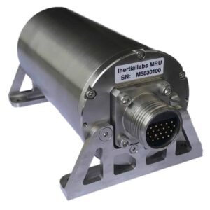
Inertial Labs is a leading designer and manufacturer of position and orientation tracking systems for unmanned vehicles. Our high accuracy solutions are based on the fusion of inertial navigation sensors with a range of other cutting-edge sensing technologies, including MEMS-IMU, accelerometers, gyroscopes and AHRS. With our engineering expertise, we create high-performance inertial sensor systems with small size and low power requirements.

Our products are ideal for a variety of unmanned systems applications, including motion tracking, weapon orientation tracking, payload stabilization, and inertial position tracking for GPS-denied environments.

Inertial Measurement Units (IMU)

IMU-FI-200C Inertial Measurement Unit

Tactical-grade FOG-based IMU

IMU-FI-200C FOG IMUThe IMU-FI-200C is a compact tactical-grade IMU that incorporates three-axis FOGs and three-axis high-precision MEMS accelerometers, delivering highly accurate linear acceleration and angular rate data with low noise and excellent reliability.

The sensor is fully calibrated and temperature compensated, and has been thoroughly tested to perform under significant variations in temperature, high vibration, and shock.

Highly suited to both motionless and high dynamics applications, the IMU-FI-200C is ideal for UAV and UUV navigation and control, platform and antenna stabilization, and incorporation into AHRS and INS.

Specifications:

Dimensions (D x H) 88.9 x 84.5 mm
Weight 790g
Power Consumption 5.5W @ 5V
Gyroscope Bias Repeatability 0.5 deg/hr
Gyroscope ARW 0.025 deg/√hr typical
Accelerometer Bias In-run Stability 0.015 mg
Accelerometer VRW 0.015 m/sec/√hr typical
Operating temperature -40 – +71 deg C

IMU-NAV-100 Inertial Measurement Unit

Navigation-grade high accuracy IMU

IMU-NAV-100 Inertial Measurement UnitThe IMU-NAV-100 is a lightweight and compact high accuracy IMU based on state-of-the-art MEMS sensor technologies, providing three-axis linear accelerations and angular rates with very low noise and high reliability.

Fully calibrated, temperature compensated, and mathematically aligned to an orthogonal coordinate system, the IMU-NAV-100 is highly accurate MEMS IMU in both static and dynamic conditions.

Featuring continuous Built-in Test (BIT), configurable communications protocols, electromagnetic interference (EMI) protection, and flexible input power requirements, the unit is ideal for UAV, AUV & ROV navigation and control, platform orientation and stabilization, and more. It is available in two performance variants.

Specifications:

IMU-NAV-100 Tactical A IMU-NAV-100 Tactical S
Size 59.2 x 48.2 x 48.2 mm
Weight 155 g
Gyroscope Bias In-Run Stability 0.5 deg/hr 1 deg/hr
Gyroscope Noise ARW 0.1 deg/√hr 0.04 deg/√hr
Accelerometer Bias in-run Stability 0.003 mg
Accelerometer Noise VRW 0.008 m/sec/√hr
Pitch & Roll Accuracy 0.03 deg static
0.06 deg dynamic
Power Consumption 0.8W @ 5V
Operating temperature -40 to +85 deg C

IMU-P Inertial Measurement Unit (IMU)

High Performance Tactical Grade & Industrial IMU

The IMU-P is a light-weight and compact high performance Inertial Measurement Unit, designed for a number of applications including UAV and AUV/ROV navigation and control.

The MEMS IMU contains three highly accurate Advanced MEMS gyroscopes and three ultra high performance accelerometers for precise linear acceleration and angular rate measurements.

The IMU-P is an ITAR free inertial solution, that is fully calibrated and compensated over its operating temperature range. Both Industrial and Tactical grade units are available.

Compact size (39 x 45 x 22 mm) and low weight (70 gram) – ideal for integrated system applications.

IMU-P Inertial Measurement Unit for UAVs

IMU-P Industrial and Tactical Grade IMUs

IMU-P Applications:

  • Antenna and Line of Sight Stabilization Systems
  • Motion Reference Units (MRU)
  • Motion Control Sensors (MCS)
  • Gimbals, EOC/IR, platforms orientation and stabilization
  • UAV & AUV/ROV navigation and control

Specifications:

“Industrial” IMU-P “Tactical” IMU-P
Gyroscope Bias in-run Stability 3 deg/hr 1 deg/hr
Gyroscopes noise density 0.006 deg/sec√Hz 0.004 deg/sec√Hz
Accelerometer Bias in-run Stability 0.015 mg 0.005 mg
Accelerometers noise density 0.03 mg√Hz 0.025 mg√Hz
Pitch & Roll static accuracy 0.05 deg 0.05 deg
Power Consumption 0.8 @ 5V 0.8 @ 5V
Operating temperature -40 to +85 deg C -40 to +85 deg C

Kernel Inertial Measurement Units

Fully-integrated industrial and tactical-grade IMUs

Inertial Labs Kernel IMUThe Kernel series of strapdown three-axis IMUs features the latest in MEMS IMU sensor technology, providing a number of options to suit both industrial and tactical-grade requirements.

Providing linear acceleration and angular rate outputs with three-axis MEMS accelerometers and gyroscopes, the fully-integrated IMUs are compact and lightweight and have been thoroughly tested to withstand large variations in temperature, high vibration, and shock.

The fully-calibrated tactical and industrial IMUs can be integrated into MRUs, AHRS and GNSS-INS, and are also ideal for a wide variety of drone and robotics applications such as autonomous vehicles, antenna and line of sight stabilizations systems, and vessel motion monitoring.

Specifications:

Kernel-110 Kernel-120 Kernel-210 Kernel-220
Size 28.38 x 19.5 x 10.5 mm 28.38 x 19.5 x 10.5 mm 28.38 x 19.5 x 10.5 mm 28.38 x 19.5 x 10.5 mm
Weight 10 g 10 g 15 g 17 g
Measurement Ranges ±8 /±15/±40 g ±40/±90 g ±8 /±15/±40 g ±8/±15/±40/±90 g
Gyro Bias In-Run Stability 2 deg/hr 2 deg/hr 1 deg/hr 1 deg/hr
Gyro Noise (ARW) 0.3 deg/√hr 0.3 deg/√hr 0.2 deg/√hr 0.2 deg/√hr
Accelerometer Bias In-Run Stability 0.01/0.03/0.05 mg 0.05/1 mg 0.005/0.01/0.02 mg 0.005/0.01/0.02/1 mg
Pitch & Roll Accuracy 0.05 deg static
0.08 deg dynamic
0.05 deg static
0.08 deg dynamic
0.05 deg static
0.08 deg dynamic
0.05 deg static
0.08 deg dynamic

Digital Tilt Sensors

OS3D-DTS Digital Tilt Sensor

High Accuracy, Miniature MEMS Digital Tilt Sensor

The OS3D-DTS is an ultra-high accuracy, miniature dual axis MEMS Digital Tilt Sensor, designed for precision tilt measuring. It includes tri-axial MEMS Gyroscopes and tri-axial high precision MEMS Accelerometers; and is equipped with an onboard processor and embedded inclination and tilt algorithms allowing for direct integration into systems without interfacing a PC.

The low-SWaP, ITAR-free OS3D-DTS is environmentally sealed (IP67) in a rugged enclosure, making it ideal for a wide range of unmanned applications, including UAVs, Robotics and Electro Optical Systems.

OS3D-DTS MEMS Digital Tilt Sensor

Digital Tilt Sensor Applications:

  • Robotics
  • Remote Weapons Stations (RWS) stabilization and pointing
  • Electro-Optical Systems (EOS) stabilization

Specifications:

Size 26.5×19.5×7.4mm
Weight 9 grams
Power Consumption 125 mW (typical)
Pitch & Roll Resolution 0.01 deg
Pitch & Roll Accuracy 0.05 deg
Bandwidth up to 200 Hz
Operational Temperature Range -40 to +85 deg C

More Information: OS3D-DTS Digital Tilt Sensor

Attitude and Heading Reference Systems (AHRS)

AHRS-10 – High Accuracy AHRS

The AHRS-10 is a high-accuracy AHRS that outputs absolute orientation (heading, pitch and roll) for both motionless and dynamic applications. It integrates precision 3-axis accelerometers, magnetometers and gyroscopes to provide absolute pitch and roll data, real time device rotation data and ongoing gyroscope corrections.

The AHRS-10 utilizes our high-performance Fluxgate Magnetometer technology for superior stability and repeatability, making it an ideal solution for unmanned systems applications where superior accuracy is required.

AHRS-10 – High Accuracy AHRS

Applications:

  • Point-to-point antenna stabilization and motion control
  • Antenna Reference Units (ARU)
  • Radar Reference Units (RRU)

Specifications:

Model AHRS-10B AHRS-10P
Size 90×27×26mm 90×27×26mm
Weight 77 grams 843 grams
Heading Accuracy 0.8 deg static, 1.0 deg dynamic 0.3 deg static, 0.6 deg dynamic
Pitch & Roll Accuracy 0.2 deg static, 0.5 deg dynamic 0.1 deg static, 0.3 deg dynamic
Gyroscope Bias in-run Stability 8 deg/hr 1 deg/hr
Accelerometer Bias in-run Stability 0.005 mg 0.005 mg
Magnetometer bias in-run stability 0.8 nT 0.2 nT

AHRS-II – Absolute Orientation AHRS

The AHRS-II is our family of next-generation AHRS featuring state-of-the-art algorithms for a wide range of dynamic motions of unmanned vehicles. Precision 3-axis accelerometers, magnetometers and gyroscopes provide heave, heading, pitch and roll data, as well as high-frequency real time device rotation data and ongoing gyroscope corrections.

AHRS-II Absolute Orientation AHRS

OptoAHRSTM-II works through the use of reference images. A reference image is literally a picture of the horizon in a given direction. Within the reference image the system identifies a constellation of identifiable features.

Applications:

  • Antenna pointing systems
  • Geospatial systems

Specifications:

AHRS-II-P Absolute Orientation AHRS OptoAHRS-II Absolute Orientation AHRS
Model AHRS-II-P OptoAHRS-II
Size 120 x 50 x 53 mm 132 x 60 x 47 mm
Weight 220g 600g
Heading Accuracy 0.3 deg <0.2 deg
Pitch & Roll Accuracy 0.1 deg 0.08 deg
Gyroscope Bias in-run Stability 1 deg/hr 1 deg/hr
Accelerometer Bias in-run Stability 0.005 mg 0.005 mg
Magnetometer Bias in-run Stability 0.2 nT 0.1 nT

miniAHRS – Miniature AHRS

The miniAHRS is a lightweight, compact AHRS that is ideal for integration into small drones and unmanned systems. The device combines 3-axis accelerometers, magnetometers and gyroscopes to provide absolute pitch and roll data, real-time three-axis rotation measurement, and ongoing gyroscope corrections.

miniAHRS – Miniature AHRS

The miniAHRS features advanced Kalman filter-based sensor fusion techniques as well as state-of-the-art algorithms for the dynamic motions of different unmanned vehicles and robotic platforms in land, sea and air domains.

miniAHRS Applications:

  • Low-SWaP UAVs and unmanned systems
  • Weapons systems fire control

Specifications:

Size 53 x 19 x 13 mm
Weight 20g
Heading Accuracy 0.3 deg static, 0.6 deg dynamic
Pitch & Roll Accuracy 0.1 deg static, 0.2 deg dynamic
Gyroscope Bias in-run Stability <4 deg/hr
Accelerometer Bias in-run Stability 0.005, 0.02, 0.03 mg (±8/±15/±40 g measurement ranges)
Magnetometer Bias in-run Stability 8 μGauss

More Information: miniAHRS – Miniature AHRS

GPS-Aided Inertial Navigation Sensors

GPS-INS for Unmanned Vehicles

INS-DU Dual-Antenna GPS-INSOur family of GPS-Aided Inertial Navigation Systems combines support for multi-GNSS constellation signals (L1 & L2 GPS, GLONASS, GALILEO and BEIDOU) with state-of-the-art 3-axis accelerometers, magnetometers and gyroscopes to provide accurate position, velocity, heave and absolute orientation data for both unmanned aircraft and ground robotics. Both single- and dual-antenna GPS-INS are available.

Single-Antenna GPS-INS

Our single-antenna GPS-aided INS is available in three models. Both the INS-P and INS-U incorporate an embedded high-precision gyro-compensated magnetic compass for enhanced heading performance in GNSS-denied environments, even under highly challenging environmental conditions.

The INS-U also features an integrated Air Data Computer (ADC) that outputs parameters such as static and dynamic pressure, airspeed, Mach number and angle of attack.

Specifications:

INS-B GPS-Aided Inertial Navigation System INS-P GPS-Aided Inertial Navigation System INS-U
Model INS-B (Basic) INS-P (Professional) INS-U
Size 120 x 50 x 53 mm 120 x 50 x 53 mm 82.0 x 40 x 26 mm
Weight 220g 280g < 200g
Position Accuracy 1.5 m (GPS L1)
1.2 m (GPS L1&L2)
0.6 m (SBAS)
0.4 m (DGPS)
0.05 m (PP)
0.01 m + 1 ppm (RTK)
1.5 m (GPS L1)
1.2 m (GPS L1&L2)
0.6 m (SBAS)
0.4 m (DGPS)
0.05 m (PP)
0.01 m + 1 ppm (RTK)
1.5 m (GPS L1)
1.2 m (GPS L1&L2)
0.6 m (SBAS)
0.025 m (PPP)
0.01 m + 1 ppm (RTK)
Heading Accuracy
(static | dynamic)
1 deg | 0.1 deg 0.4 deg | 0.1 deg 0.3 deg | 0.6 deg
Velocity Accuracy 0.03 m/sec 0.03 m/sec 0.05 m/sec
Pitch & Roll Accuracy
(dynamic)
0.1 deg 0.1 deg 0.08 deg
Gyroscope Bias in-run Stability 1 deg/hr 1 deg/hr 2 deg/hr
Accelerometer Bias in-run Stability 0.005 mg 0.005 mg 0.01 mg (±8g)
0.03 mg (±15g)
0.05 mg (±40g)

Dual-Antenna GPS-INS

Our dual-antenna GPS-aided INS sensors provide enhanced accuracy for unmanned vehicle positioning and heading in both static and dynamic conditions.

Specifications:

INS-BU Dual-Antenna GPS-Aided INS INS-D GPS-Aided Inertial Navigation System Inertial Labs INS-DL Dual-Antenna GPS-INS INS-DU Dual Antenna GPS INS INS-DM Dual Antenna GPS INS
Model INS-BU INS-D INS-DL INS-DU INS-DM
Size 120 x 50 x 53 mm 120 x 50 x 53 mm 120 x 50 x 53 mm 120 x 50 x 53 mm 160.4 x 141.2 x 61.1 mm
Weight 320g 320g 320g 320g 1345g typical
(depends on configuration)
Horizontal Position Accuracy 1.5 m (GPS L1)
1.2 m (GPS L1 & L2)
0.005 m (PP)
0.01 m + 1 ppm (RTK)
1.5 m (GPS L1)
1.2 m (GPS L1 & L2)
0.6 m (SBAS)
0.4 m (DGPS)
0.005 m (PP)
0.01 m + 1 ppm (RTK)
1.5 m (GPS L1)
1.2 m (GPS L1 & L2)
0.4 m (DGPS)
0.005 m (PP)
0.01 m + 1 ppm (RTK)
1.5 m (GPS L1)
1.2 m (GPS L1 & L2)
0.005 m (PP)
0.01 m + 1 ppm (RTK)
1.2 m (SP)
0.6 m (SBAS)
0.4 m (DGPS)
0.005 m (PP)
0.01 m + 1 ppm (RTK)
Heading Accuracy
(static | dynamic)
0.6 deg | 0.3 deg 0.15 m | 0.08 m
(1m | 2m baseline)
0.2 m | 0.08 m
(1m | 2m baseline)
0.2 m | 0.2 m
(2m baseline)
0.4 m | 0.4 m
(1m baseline)
0.15 deg | 0.15 deg
(1m baseline)
0.08 deg | 0.08 deg
(2m baseline)
Velocity Accuracy 0.05 m/sec 0.03 m/sec 0.03 m/sec 0.05 m/sec 0.03 m/sec or 0.05 m/sec
(depending on receiver)
Pitch & Roll Accuracy
(dynamic)
0.03 deg RMS 0.08 deg RMS 0.1 deg RMS 0.2 deg RMS 0.01 – 0.05 deg
(depending on IMU)
Gyroscope Bias in-run Stability 2 deg/hr 1 deg/hr 3 deg/hr <2 deg/hr 0.25 – 2 deg/hr
(depending on IMU)
Accelerometer Bias in-run Stability 0.01 mg (±8 g) 0.005 mg (±8 g) 0.005 mg (±8 g) 0.005 mg (±8 g) 0.003 – 0.025 mg
(depending on IMU)

Dual Antenna GPS-Aided INS OEM

OEM INS Solutions

OEM versions of our INS-B, INS-D and INS-DL industrial and tactical grade GPS-aided INS are also available. Measuring just 85 x 47 x 36 mm and weighing from 115 to 160g, they can be easily integrated onto SWaP-conscious platforms.

INS-DH-OEM dual antenna GPS-aided INSThe INS-DH-OEM is a next-generation dual antenna GPS-aided INS that features state-of-the-art sensor fusion, navigation and guidance algorithms, and incorporates an advanced NovAtel GNSS receiver and Honeywell HG4930 IMU.

Specifications:

Size 85.5 x 67.5 x 52.0 mm
Weight  280g
Horizontal Position Accuracy 1.2 m (GPS L1 & L2)
0.6 m (SBAS)
0.4 m (DGPS)
0.025 m (TerraStar-C Pro)
0.005 m (PP)
0.01 m + 1 ppm (RTK)
Heading Accuracy 0.2 deg (2m baseline) / 0.1 deg (PPK)
Velocity Accuracy 0.03 m/sec
Pitch & Roll Accuracy
(dynamic)
0.03 deg RMS
Gyroscope Bias in-run Stability 0.25 deg/hr
Accelerometer Bias in-run Stability 0.025 mg

INS Applications:

  • UAV/drone flight control systems in GPS-denied environments
  • Remote sensing
  • Low altitude photogrammetry
  • Law enforcement
  • Autonomous Vehicle Navigation Systems
  • Aerial Inspections – roads, bridges, power lines
  • Surveying / 3D mapping
  • Precision Agriculture
  • Military inspections
  • ADAS – Advanced Driver-Assistance Systems

Two and Three Axis Gyroscopes (TAG)

Tactical-grade multi-axis Gyros for stabilization & pointing

The TAG-200 and TAG-300 are tactical-grade two- and three-axis MEMS gyroscopes designed for stabilization and pointing.

With low SWaP, noise and latency as well as a wide bandwidth, they are ideal for complex unmanned systems applications.

Tactical-Grade Gyro TAG-200

TAG gyros are engineered to withstand the harshest environments, with no moving parts and tested to MIL-STD-810 levels of shock and vibration. They are factory-calibrated over the entire operation temperature range, and precision-machined to ensure extremely low non-orthogonality and misalignment between sensitive elements.

Tactical-Grade Gyro TAG-300

TAG Multi-Axis Gyro Applications:

  • Remote Weapons Stations (RWS) stabilization and pointing
  • Electro-Optical Systems (EOS) image stabilization
  • Offsetting UGV and land vehicle pitch and roll.

Specifications:

Number of Axis Two (TAG-200); Three (TAG-300)
Size 39 x 45 x 22 mm
Weight 70g
Power Consumption 0.8 W @ 5V
Measurement Range: ±450, ±950, ±2000 deg/sec
Data update rate: 2000 Hz
Bias in-run stability: 2 deg/hr (Allan Variance, RMS)
Noise (ARW): 0.08 deg/√hr

More Information: TAG Multi-Axis Gyros

Motion Reference Units (MRU)

High Performance Motion Sensors

Our Motion Reference Units are high-performance strapdown motion sensors specifically designed for marine applications such as ROVs. Utilizing precision solid state 3-axis accelerometers, magnetometers, gyroscopes and barometric sensors, the units output highly accurate position, velocity, acceleration, heading, pitch & roll, and heave, sway & surge data.

MRU-E ROV Motion Reference Units

The Motion Reference Units are available in three different models – Basic, Enhanced and Professional – to provide desired levels of accuracy and stability as well as the required outputs for your particular application.

MRU-B Subsea Motion Reference Units

MRU Applications:

  • Marine surveys
  • Hydrography
  • Bathymetry

Video: MRU Qualification Tests

Model Comparison: Measured Parameters

MRU-B Subsea Motion Reference Units MRU-E ROV Motion Reference Units MRU-P ROV Motion Reference Units
Model MRU-B (Basic) MRU-E (Enhanced) MRU-P (Professional)
Heave (% / cm)
Pitch & Roll (deg)
Heading / Yaw (deg)
Velocity (meters / sec)
DGPS / RTK Positions (meters)

Specifications

Model MRU-B (Basic) MRU-E (Enhanced) MRU-P (Professional)
Size 120 x 50 x 53 mm 120 x 50 x 53 mm 120 x 50 x 53 mm
Weight 220g 280g 320g
Position Accuracy N/A N/A 0.01 m + 1 ppm (RTK)
Heave accuracy 5% / 5cm 5% / 5cm 5% / 5cm
Heading Accuracy
(static | dynamic)
N/A 0.6 deg | 0.1 deg 0.4 deg | 0.1 deg
Velocity Accuracy N/A N/A 0.03 m/sec
Pitch & Roll Accuracy
(dynamic)
0.08 deg | 0.03 deg 0.08 deg | 0.03 deg 0.08 deg | 0.03 deg
Gyroscope Bias in-run Stability 1 deg/hr 1 deg/hr 1 deg/hr
Accelerometer Bias in-run Stability 0.005 mg 0.005 mg 0.005 mg

More Information: Motion Reference Units

Wave Sensors (WS)

High performance Wave, Direction & Motion Sensors

The WS-E (Enhanced) and WS-PD (Professional Dual) are high-performance strapdown wave direction and motion sensors that provide accurate wave characteristics as well as heave, sway, surge, pitch and roll data for USVs and other floating marine platforms.

The Wave Sensors can be interfaced with external GNSS receivers, gyro compasses and Doppler Velocity Logs (DVL), and can output spectral data as a complete set of Fourier coefficients and energies.

High performance Wave Sensors

Wave Sensor Applications:

  • Ocean monitoring on buoys, USVs and AUVs

Model Comparison: Measured Parameters

 WS-E (Enhanced) Wave Sensor  WS-PD (Professional Dual) Wave Sensor
Model WS-E WS-PD
Wave Height (meters)
Wave Period (sec)
Wave Direction (deg)
Heave, Surge, Sway (%/meters)
Pitch & Roll (deg)
Gyro-magnetic Heading (deg)
High Precision GNSS Heading (HDT) (deg)
DGPS/RTK Position (meters)

Specifications

Model WS-E WS-PD
Size 120 x 50 x 53 mm
Weight 320g
Position Accuracy External Source 40 cm (DGPS)
1 cm (RTK)
Wave Period Accuracy 1% / 0.1 sec
Wave Height Accuracy 5% / 0.05 m
Wave Direction Accuracy 1 deg 0.5 deg
Pitch & Roll Accuracy 0.02 deg
Heading Accuracy 0.6 deg 0.05 deg

More Information: Wave Sensors

RMCU – Railway Motion Control Unit

The RMCU is a high-performance strapdown system specially designed to determine absolute orientation (heading, pitch and roll) and parameters of motion (angular rates and linear acceleration) for railway platforms in both static and dynamic situations.

The system is compliant with EN 45545, EN 50155 and EN 50011 railway standards and features state-of-the-art embedded algorithms for different railway platforms.

RMCU – Railway Motion Control Unit

RMCU Applications:

  • Railway crack detection analysis
  • Safer and more reliable components for the railway industry
  • Aiding data for robust railway navigation systems

Specifications:

Size 129 x 53 x 49 mm
Weight 120g
Heading Accuracy 0.3 deg static, 0.6 deg dynamic
Pitch & Roll Accuracy 0.05 deg static, 0.08 deg dynamic
Gyroscope Bias in-run Stability <4 deg/hr
Accelerometer Bias in-run Stability 0.005, 0.02, 0.03 mg (±8/±15/±40 g measurement ranges)
Magnetometer Bias in-run Stability 8 μGauss

RESEPI – Remote Sensing Payload Instrument

Flexible LiDAR point cloud generation solution for UAVs

RESEPI Remote Sensing Payload Instrument

RESEPI is a high-accuracy LiDAR point cloud generation solution designed for Inertial Labs partners and sellers to white-label, allowing them to customize both the hardware and software with their own branding and focus on their core competencies without worrying about additional development.

RESEPI Flexible point cloud solution for UAVs

Built around a Linux-based processing platform, the modular system includes Inertial Labs’ own high-performance dual-antenna GPS-aided inertial navigation system (INS) with a dual-use NovAtel RTK/PPK GNSS receiver, as well as Wi-Fi communications and an embedded cellular modem for in-flight RTCM RTK corrections.

RESEPI supports a wide range of leading LiDAR scanners from providers such as Velodyne Lidar, Quanergy, Livox, Hesai and Ouster, as well as RGB and thermal cameras for combined photogrammetry and point cloud generation.

Remote Sensing Payload
Remote Sensing Payload with Quanergy
Remote Sensing Payload with Avia
Remote Sensing Payload with Hesai
Remote Sensing Payload with Ouster

Thanks to Inertial Labs’ cutting-edge orientation and positioning technology, RESEPI produces extremely thin point clouds even at a high AGL. RESEPI’s software suite features fully-automated RTK LAS file generation, as well as a one-click command line interface for post-processing.

RESEPI is ideal for a wide range of UAV remote sensing applications, including:

  • Mapping and Scanning
  • Precision Agriculture
  • Simultaneous Localization and Mapping (SLAM) Algorithm Development
  • Infrastructure and Utilities Inspection
  • Construction Site Monitoring

Specifications:

Weight (without LiDAR) 0.37 kg
Power Consumption (with VLP-16 LiDAR) 12W
Position Accuracy 0.5 cm (PPK estimated) / 1 cm + 1 ppm (RTK)
Attitude Accuracy <0.01 deg Pitch & Roll, <0.05 deg Heading
Point Cloud Precision 3 – 5 cm (dependent on LiDAR, taken on the same target @ 50 m AGL)
Max Altitude 200m AGL
Products
+ Load More Products
Articles
+ Load More Articles
Regional Offices & Locations
Inertial Labs United States of America 39959 Catoctin Ridge Street, Paeonian Springs, VA 20129 U.S.A. +1 703-880-4222 Contact Website