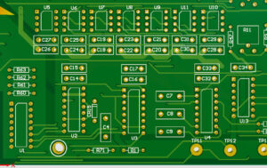
 San Francisco Circuits has created a new resource on PCB assembly drawings covering polarities, Pin1 marking and anode/cathode markings.
In the realm of printed circuit board (PCB) manufacturing and assembly, attention to detail is paramount. Every element, from component placement to orientation, plays a crucial role in ensuring a successful and efficient assembly process. One vital aspect of this process is the proper utilization of the assembly drawings; in particular, the significance of polarities, Pin1 marking, and anode/cathode markings.
The guide covers:
- The role of rotations and component orientations
- Polarized components
- Component placement best practices
Precise and accurate PCB assembly drawings are critical for a successful manufacturing and assembly process. Paying close attention to these details ensures that components are correctly assembled, reducing the risk of errors or failures.
By adhering to industry standards and leveraging advanced software tools, designers, manufacturers, and assembly providers can enhance the efficiency and reliability of their PCB assembly processes.


