Blue Marble Geographics’ Global Mapper version 25.1 has arrived with new data display options and fresh new tools.
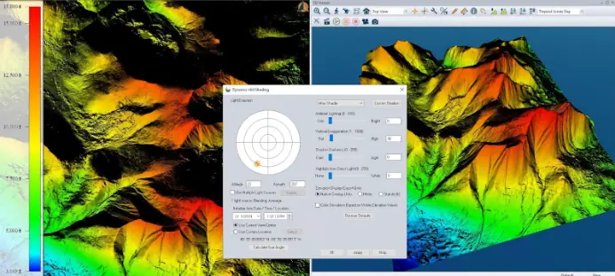
Notably, the hillshade tool now boasts the ability to create shadows across the terrain layer based on location and time of day, modeling the real-world sun angle.
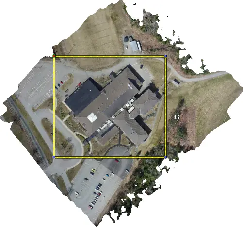
Improving Global Mapper’s vast data editing tools, version 25.1 includes the ability to crop a mesh feature, such as those generated by pixels to points, using a rectangle. For users who pair Global Mapper with positioning devices, version 25.1 can receive location data from GNSS devices over TCP and UDP, including support for Trimble devices, matching the capabilities of Global Mapper Mobile.
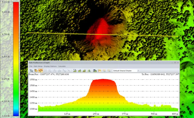
Building on the Path Profile updates in Global Mapper Pro, the Standard version brings ease-of-use updates to the setting dialog and the ability to apply terrain shaders to elevation data. Other data display updates include improvements to the 3D viewer, such as a new 3D Feature Info tool and more accurate point feature scaling.
All listed features are available in both Global Mapper and Global Mapper Pro, but Pro features are limited to Pro. As always, the complete list of new features, updates, and bug fixes is included in the v25.1 Knowledge Base.
Interested in the new Pro features in 25.1? Check out this blog: Top New Features in Global Mapper v25.1 Pro.
Automatically Calculate the Sun/Shadow Position Based on Location, Date, and Time
The Hilshade tool in Global Mapper displays directional shadows on terrain data. It’s useful for visualizing terrain texture, estimating shadows, and more. Version 25.1 has enhanced this tool by adding the option to calculate the sun’s Azimuth and Altitude based on time at a specified location. Using either the data’s location or an input location, you can give Global Mapper a date and time, which it will use to calculate the sun’s location for display in the 2D and 3D workspaces automatically. This gives users the power to visualize which areas will receive sunlight throughout the day at any point during the year. The date and time settings are automatically localized to the data’s location; no worries about taking time changes into account.
Vector Feature Info Tool in 3D Viewer
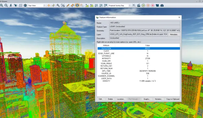
The Feature Info tool is a staple function of Global Mapper that provides the ability to view attribute data of a feature directly from the workspace. An extension of the Feature Info tool has now been implemented in the 3D viewer for vector and point cloud data. It can be accessed through a new icon in the 3D viewer toolbar. Functioning similarly to the 2D version, you can click on a lidar point to view its metadata, or on a vector feature to display all attribute information associated with the selected feature. The selected vector feature will also be selected in the 2D view, and will also include editing options for adjusting the data values.
Note that similar to the digitizer tool, the sidewall area features that are artificially extruded to the surface (such as buildings) cannot be selected. The extruded features are not real, but the vertices that they are drawn from are and can be selected. Use the Edit and Vertices functions in the Feature Info tool to make changes to the data and see them applied in the 3D viewer.
New Settings and Elevation Shader in Path Profile
Following the reorganization of the dropdown Analysis menus in Global Mapper itself, the Path Profile settings have also been separated by function for ease of use. There are now three tabs: General Settings, Data Display, and Perpendicular/Parallel Path profiles.
Another new functionality in the path profile tool is the ability to color terrain data in the Path Profile view using elevation shaders, including custom elevation shaders.
This helps to improve data visualization in the path profile window and eases data interpretation against the workspace view. Further color customization options for background color, text color, font, and more can be found by right-clicking in the path profile window.
Create Parallel Profile Lines
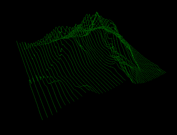
The path profile tool now supports parallel profile paths in addition to the existing perpendicular profile paths. These series of cross-sectional views of terrain or point cloud data spaced along a defined path provide the ability to look at subsections of the path profile. Use parallel and perpendicular paths to explore sections of terrain data one area at a time. Parallel profiles can be created from single-segment line paths, that is to say, lines with no turns or extra vertices.
These paths can also be exported as line features that trace the highest elevation values of the terrain, as shown in the image below. Perspective paths are a great way to export linear terrain data to modeling software that isn’t able to handle complex or terrain data as Global Mapper can.
Mesh Cropping
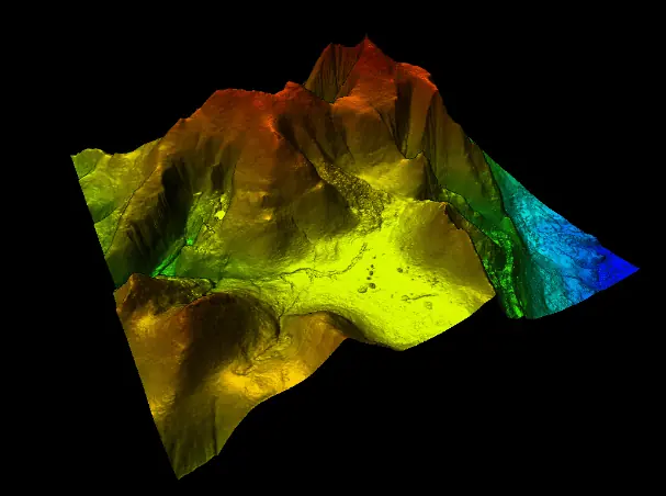
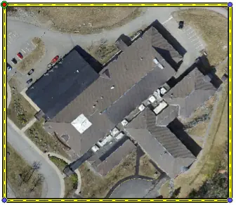
The long-requested ability to crop a mesh feature is here! Global Mapper has always been able to crop vector, raster, and lidar data, but mesh layers are differently structured. Meshes are made up of both vertices and polygons that define the shape of an object or terrain. The new mesh cropping function can cut the edges of a mesh layer to fit the layer bounds of a selected rectangle area feature. If the selected area feature isn’t a rectangle, the layer’s bounding box will be used. Simply select the area feature, open the crop tool, and be sure to check the Meshes and Mark Cropped Features Deleted boxes. (Want to undo the crop? Use ctrl Z on your keyboard to undo recent actions.)
This is especially useful in Pixels to Points with drone-collected imagery. Photogrammetry creates 3D data based on what it can see in images. This works very well for the main part of the study area, but on the periphery, where there is less image coverage and, therefore, less data to build from, the generated mesh edges can be less crisp than desired. (Note: this is why it’s often beneficial to capture buffer imagery a bit outside of the study area.) With the addition of mesh cropping, users are now able to restrict the bounds of mesh features to a predefined area.
Generate STL Files Tailored for 3D Printing
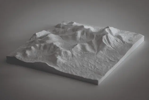
Global Mapper has been able to export STL 3D files since version 16. Now, version 25.1 includes a dedicated STL export option designed to streamline the process of preparing an export for 3D printing. These options include the ability to scale the final model in inches, centimeters, or millimeters to help you determine the proper size for ensuring that the file will load properly in your slicer and fit on your print bed. Use the base options to generate a base and sidewalls automatically, and the base thickness option to determine how far below the lowest elevation the base should extrude. Note that if you set the base thickness to “0,” this may create a hole or thin spot in your model, depending on your print layer thickness. Use the Z Scalar option to exaggerate changes in height, similar to the 3D Viewer’s Vertical Exaggeration setting.
To check out the new functionality in Global Mapper standard and Pro v25.1, download a free 14-day trial today.


