


Omnetics explain the use of eVTOL wiring and connection systems, including a specialty check list that can help users select or design the right connection system for their unmanned aircraft.

An Evolution in Flight details: The big steps in today’s eVTOL include much more than what first meets the eye, however. Early UAVs and drones, began expanding the data processing and onboard sensor usage and includes satellite coordination, advance surveillance imaging and higher speed digital data processing modules. Newer electrically driven vertical craft have added additional functions needed in human passenger services and safety, as well. As the passenger count climbs, the vehicle weight increases and this requires more robust vertical lift systems.

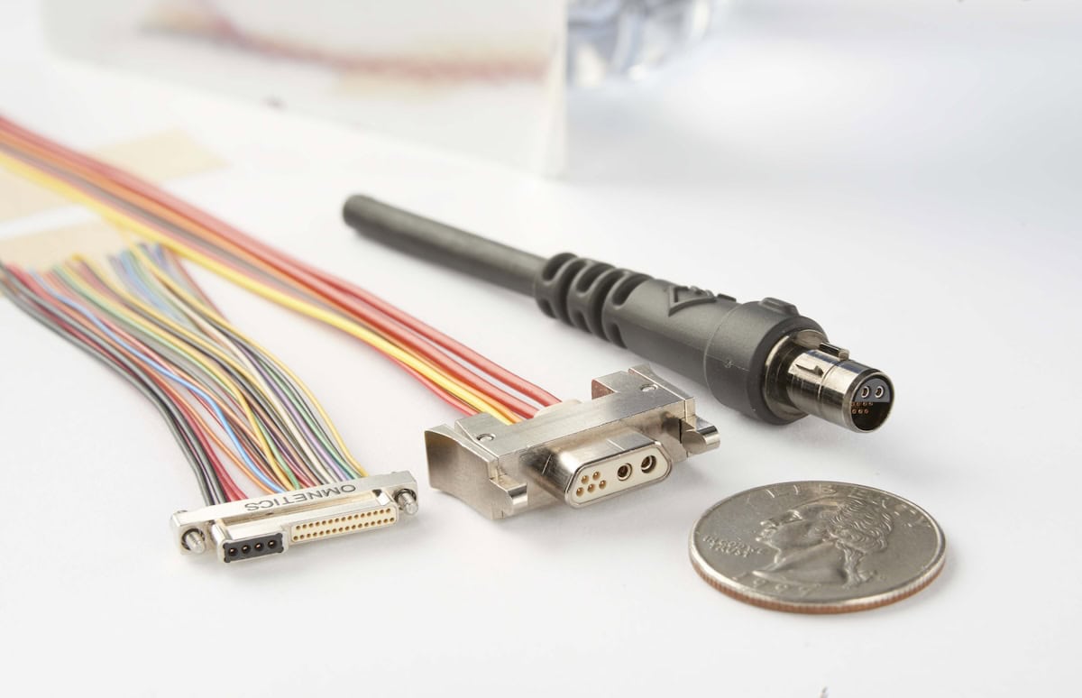
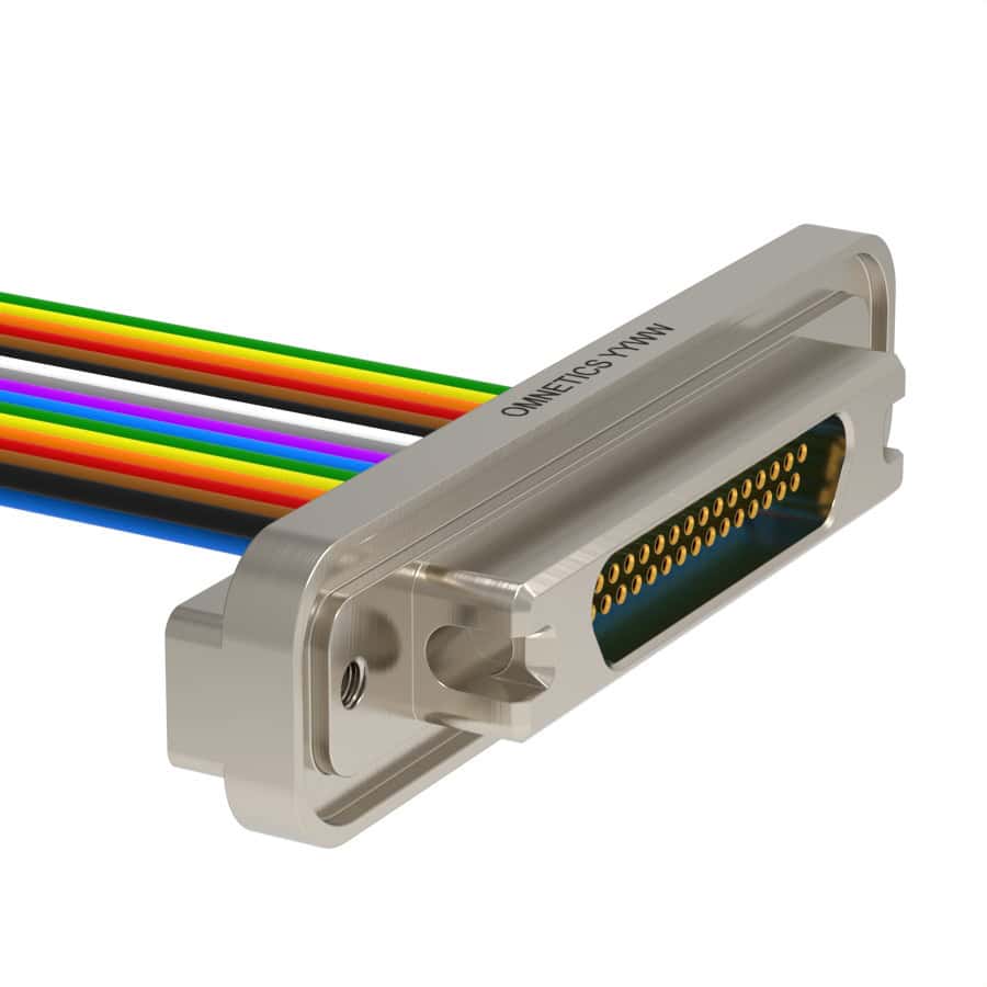
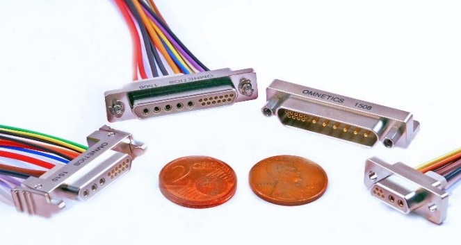
New cable and connector networks will contain many individual and combinations of signal and power routing needs varying from focus on high speed digital detection and direction signaling to power routing to detectors and actuators. Cables will also vary in length, flexibility, size and weight. In some cases, cable and connectors will also need to include shielding and cable braiding for high density signal packing and to provide noise abatement from external sources. We have built a specialty check list that may help in selecting the right connection system and or in custom designing exactly what fits and serves the whole aircraft in the best way.

eVTOL wiring systems can be grouped into the types of wire and electrical service they perform in the listing below:
- High current and power delivery for Rotor drive for lift and or thrust and direction control.
- Flight control data and cockpit instrumentation.
- Micro-wave and RF data received from satellite and radio connections.
- Sensor data collection for performance and positioning such as GPS or Surveillance.
- Mixed signal wiring that serves instruments requiring power, and signal data within one cable.
- Passenger comfort wiring for entertainment, cockpit communications to the cabin.
- Flight attendant, lighting and passenger safety.
- Variations in cable design may be required for sensors reporting malfunctions, instrument temperature, fuel or energy levels. As eVTOL craft are employed for Urban transport networks new designs for craft mapping and collision avoidance will be required.

Similarly, machine drives that signal rotor angles, or sensor monitors on gyros and detectors must often be small, limp, lightweight and eventually be routed into a cockpit or control computer. Electrical circuit format from device to device will span the range from analog and power for relays and current source instruments to very low voltage and milliamp digital signals running up to 5 Gigabits per second.
Focusing more on Micro and Nano-wiring systems often requires specific attention to insure low voltage signal integrity for use in in eVTOL DESIGN. Power wire and connector systems have been covered and explained widely in previous technical papers and necessarily so. Recognizing each specific device on the system can help significantly as well as where it is exposed physically and the circuit technology it must match up with. As an example; GPS devices gather info from RF transmissions sent by LEO satellites and then must route that data to an instrument panel computer. Image cameras take photos outside the craft but must run through a processor to a display on the instrument panel. Altimeter and gyro sensors collect data for the flight computer etc.
The connector and cable designer must insure their interconnection is designed to survive and perform well beyond the standard specifications in truly extreme environments beyond the standard specifications. Rather than looking at testing connectors to pass general specifications, the system designer must begin a specific check list that focuses on the worst of times. It is also important to remember that “extreme performance” can range from a product operation in well controlled environments but must endure very high speed motion with millions upon millions of operations a day. By using a check list to compare potential hazards, one can define more about the best connector materials to use, what method of latching, or sealing or insulating is needed. Each portion of the connector and cable should be reviewed against the list. Omnetics focuses its miniature connector system on extreme environmental use where many consumer connectors do not.
Application-specific connectors and cables have come of age with the coupling of automated machining equipment and 3-D printing of first article products. Most often a solid model can be completed with two to three days for the design team to review.
Frequent reference to the harsh-environmental conditions will keep design on track and assure better performance in the end. One simplified list focuses on a mix of connector and environmental situations is shown below.
EVTOL CONNECTOR AND CABLE DESIGN CHECK LIST
| Mechanical | Electrical Signal | Cable Design | Environmental |
| Physical abuse | Signal integrity | Outer jacket | Thermal Cycles |
| Shock | Voltage / Current level | Diameter/ Weight | U.V. or IR Exposure |
| Vibration | Signal speeds. | Bend radius | Petroleum exposure |
| Temperature | Noise effects | Frequency of Bends | Chemicals/ Battery acid |
| Locking Mechanism | Impedance | Stress in length | Dust/ Wind exposure |
| Water, depth and time | Digital Diff. Signals | Crush resistance | Explosion resistance |
| Number of Mates | EMI –Ingress / Out. | Immersion resistance | Outgassing Materials |
| Corrosion potential | Cable length vs signal | Chem. / Salt exposure | Testing of systems to meet Specifications |
| Salt, Acid exposure | RF signal protection | Round or Flat | |
| Acceleration | Connection Resistance | Number of Wires | |
| Circular or Rectangular | Surge current protect | Metal Shield Need | |
| Materials Compliance | Ground Return | VP of differential wires | |
| Pin spacing vs speed | Dielectric of Connector Insulators | Coax insulation dk. |
In Addition: Work directly with your Connector and Cable Design Team to insure sections must meet required standards such as ES 3474 and AS4373.

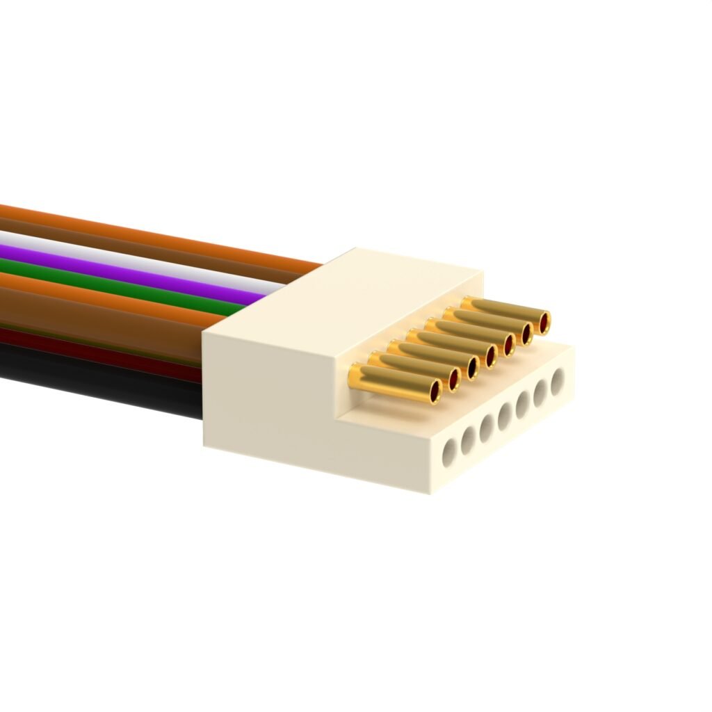
Saving Weight and Size while adding Sensors into the system. By focusing on the data acquisition from sensors, we most often only need smaller wire and cable routed back to the main instrumentation area. Circuit modules can be stacked and or assembled in low profile assemblies. The connectors on internal circuit boards and processors can be selected to save size and weight as well as offer extra circuit board space for higher density packing. Ruggedized Micro and Nano-connectors are separately wired to sense and detect devices for digital signal routing within the vehicle. This allows multiple sites for aircraft functions like attitude management, rotor angle monitoring, and image sensors, connections to and from satellite monitoring systems for GPS and communications are often used for USB data routing within the craft as well. It is critical that the miniature connectors and cable used that have been tested specifically for high shock, vibration, and exposure to extreme environmental conditions.
Omnetics
When there is no standard connector; of the needed size, shape or electrical capability to meet the circuit needs, a solution is immediately available by using experienced solid modeling designers and their interactive, on-line design work sessions. System designers can sit down with the connector designer and go through his new design needs to help define the new cable and connector.
The Omnetics “Three-Step-Process”. To insure “Application Specific Connectors” will meet your needs and be available on-time!

- Designers can view miniature connectors with proven performance on our websites or discuss with our sales team. If one looks close, ask for a sample or discuss variations on email or the phone.
- Connect with an Omnetics connector designer for on-line collaboration making a new solid model of exactly what is needed. This should take less little as 2 days.
- When you like the solid models, ask for a 3-d sample made using automated material added process. This should take less than 24 hours.
The new 3-d model is shipped to the customer to fit it into his new application for final approval or/and re-define some specific change needed.