


Inertial Measurement Units (IMU)
Discover cutting-edge solutions from 18 leading global suppliersIn the below article, Nathan Miller, Staff Software Engineer for Parker‘s MicroStrain Sensor development team, offers some tips for improving the performance of inertial sensors, including:
- Isolating MEMS IMUs from vibration
- Periodically capturing gyro bias
- Using integrated delta-theta and delta-velocity instead of raw angular rate and acceleration when performing integration
- Paying close attention to time synchronization

Microelectromechanical Systems (MEMS) gyroscopes and accelerometers are smaller, lighter and more powerful than ever before. The current state of the art chips are leaps and bounds ahead of what was available a decade ago, allowing low-cost MEMS Inertial Measurement Units (IMUs), which integrate these sensors, to deliver performance on par with tactical-grade systems that were previously only found in expensive, high-end applications.
Despite massive performance improvements, MEMS IMUs still have unique characteristics users should be aware of. By accounting for these in your system and following good IMU data practices, you can be assured the best performance for your application.
Here are some tips you can utilize to improve your inertial sensor performance:
Isolate MEMS IMUs from vibration
Isolating MEMS from unwanted vibration is critical for getting accurate measurements. Users are generally interested in the overall motion of a system, such as a vehicle trajectory, and not interested in measuring vibrations.
Vibration can come from a variety of sources: system components (such as motors), resonance in the structure the sensor is attached to due to motion over terrain, or even vibrations generated by people walking nearby. By mounting the IMU thoughtfully, perhaps on a vibration isolation platform, you can minimize these effects and improve sensor performance. Not only is vibration isolation important for data accuracy, it will also improve the longevity of your system. Even the most rugged IMUs contain sensitive elements that can be damaged by exposure to high shock events.
MEMS sensors also have a noise component that is generated in the presence of vibration, called Vibration Rectification Error (VRE). That is, the oscillatory vibration signal is rectified into an undesirable bias shift in the sensor output, adversely affecting the accuracy of the measurements. By minimizing the vibration induced on the IMU, you minimize the error and increase overall system performance.
Periodically capture gyro bias
All gyroscopes suffer from a combination of effects that cause variability in their turn-on bias, or the non-zero offset they output when no input rotation is applied. This error is more significant in MEMS sensors and is the reason MEMS sensors cannot currently be used to ‘gyro-compass’.
Gyrocompassing: the process of determining a device’s heading by sensing the Earth’s rotation rate.
If you are using an Attitude and Heading Reference System (AHRS) or Inertial Navigation System (INS), the filtering algorithm in these devices estimate this bias in real-time, but it takes time, sometimes on the order of minutes, for the filter to settle on an accurate bias value. If you are using a basic IMU to read angular rate measurements, it will not be able to estimate this bias. In either of these cases, it is best to periodically capture this bias, as doing so will optimize your device’s performance.
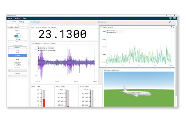
Capturing the bias requires your device to remain stationary for the capture period. It is important that any sources of vibration, such as a vehicles engine, are also off for this process. In Parker’s MicroStrain devices, you can either use the SensorConnect application or the MIP SDK to initiate the capture. After a few seconds, the device will have estimated the bias and stored it in its internal memory. Periodically performing this operation is the best way to counter gyro aging effects in your application.
Use integrated delta-theta and delta-velocity instead of raw angular rate and acceleration when performing integration
Today’s MEMS IMUs have high data rates, on the order of 1 kHz or more! If you are designing a system that requires mathematically integrating the angular rate and acceleration information, such as a navigation filter, it may be tempting to use the angular rate and acceleration outputs directly. The units for these values are familiar and if you look at standard physics equations, you would see them enumerated directly (e.g. F = ma.) But IMUs typically output a different set of quantities that are more useful: the time integral of angular rate, called delta-theta, and the time integral of acceleration, called delta-velocity. The benefits of using these instead of the instantaneous representations are the following:
- These integrals incorporate the complex coning and sculling effects the device is subject to as it rotates and accelerates when subjected to real-world motion. Accounting for these effects means the delta-theta and delta-velocity values are more accurate than integrating the instantaneous values in the typical fashion, even at the maximum rate.
- Because the IMU does this integration for you at the fastest rate, you can request these values at a much lower rate, sparing your system valuable CPU cycles. For instance, if the device natively reports data at 1,000 Hz, but your filter only needs information at 50 Hz, by using these integrals, you save yourself 20x the number of calculations while increasing the accuracy. This increase in accuracy comes from the IMU capturing the dynamics at the maximum rate while accounting for the coning and sculling effects.
Pay close attention to time synchronization
At some point in your IMU journey, you’ll probably learn that timing is everything! The importance of accurate timestamping and time-alignment are often overlooked until late in product development. If you haven’t accounted for it and your system isn’t working as expected, then you may have just found your problem.
Inaccurate time synchronization causes apparent scale-factor errors for inertial measurements. For example, when your system’s clock and the IMU’s clock are not synchronized, you will be accumulating small errors due to the drift between the clocks that has the same effect as if the IMU’s angular rate and acceleration outputs were multiplied by an errant scale factor. As the dynamics of your system increase, so does this error.
The more demanding the application, the more time alignment matters.
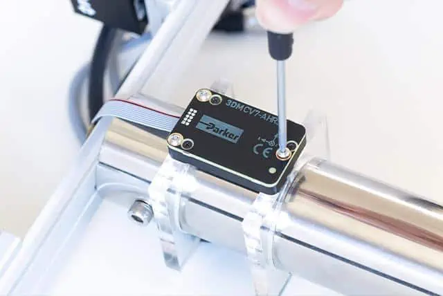
There are 2 approaches to mitigate this: align all the clocks in your system using a precision reference (hardware pulse or otherwise) and compensate for any misalignment of events algorithmically or have an IMU capable of event-generated data. The first approach is common, but often quite complex to implement across a system with many components. The second approach is something Parker has added to the 3DM-CV7-AHRS to assist our customers with exacting timing needs.
With an event-driven IMU, hardware input pulses can generate software messages (or vice versa), allowing previously difficult to process events to align nicely. For instance, in visual odometry, it is important to know the integrated IMU output from one camera frame to the next. Without an event-driven IMU, this can get quite tricky, but with one, it becomes quite simple: wire the camera’s shutter output pin to the IMU and configure it to provide the delta-theta and delta-velocity outputs upon receiving the pulse. This results in exacting integrals that align with the images generated by the camera, vastly simplifying the time alignment problem in this domain. In reverse, an event-driven IMU can generate a pulse when data quantities become valid, which can be used to drive capture events on hardware, such as cameras, and maintain the same tight time alignment.
By following these simple tips, you can improve your IMU performance and get the most out of your investment. Learn more about Parker’s MicroStrain inertial sensors.