
![]()
Rob Helliar, Head of Customer Solutions at Cambridge Pixel, has authored the following article that explains how to measure radar video latency – the time it takes for data to go from the radar source to a display screen – and why.
What is radar video latency?
In the case of radar video, latency is the time it takes for data to go from the radar source to a display screen. Radar video latency is typically measured in milliseconds and the closer it is to zero the better.
Why measure it?
A large latency could result in a noticeable difference between the radar antenna rotation and its representation on the screen. The true position of targets may have changed significantly by the time they are drawn on the screen. Here at Cambridge Pixel our engineers are occasionally asked: “How can I measure the latency between receipt of a radar video signal into an HPx card (our hardware for interfacing to analogue radar video signals) and its presentation on a display?” The answer to this depends on a number of considerations:
- The acquisition and input buffering within the HPx hardware
- Processing and packetization within the sending software
- Network delays
- Scan conversion buffering and refresh timing
Thinking about each of these stages, in broad terms one might expect 40ms of latency at the analogue acquisition and buffering stage, followed by a few milliseconds of processing latency, some non-deterministic network latency (maybe 5ms), and finally about 30ms of latency at the scan conversion end. These numbers combine to give a total of around 80ms, from receipt of data at the HPx card to appearing on the client screen.
In most situations it is reasonable to assume a latency of around 100ms as a good working value. However, there are occasionally times when you may actually need to measure the latency. For example, to demonstrate compliance against a specified requirement or to ensure correct operation of some downstream system.
Our method for measuring latency
By using a suitable test source, an oscilloscope and a video camera it is possible to get a reasonable estimate for the end-to-end latency. In Cambridge Pixel’s laboratory, we built up a test system using an HPx-300 card as the source of radar signals, feeding into an HPx-346 unit. The HPx-300 card is Cambridge Pixel’s hardware card for generating analogue radar signals, based on data provided in software. The HPx-346 handles both the acquisition and distribution of radar video data.
![]()
- The HPx-300 card is driven with a special test pattern, providing a single strobe pulse at 0 degrees azimuth, generating a clear reference mark on the oscilloscope and on the computer display.
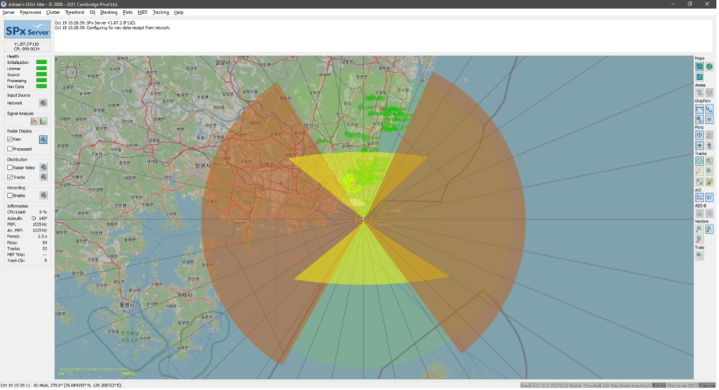
- An instance of SPx Server is also run on the client PC, to provide the scan conversion and display of the received radar video data.
- The video signal from the HPx-300 card is passed into an oscilloscope. The oscilloscope display and PC display are both captured within the same video camera feed.
- By stepping through the recording of the oscilloscope and PC display, frame-by-frame, it is then possible to measure the time between the strobe pulse first appearing on the oscilloscope and then on the PC screen. This time delay is the latency that we’re looking for.
![]()
The results
When we ran this test in our lab, the measured latency was 100ms.
It should be noted that the camera used to capture the oscilloscope and PC screens had a frame rate of 30 frames per second (FPS). Therefore, the stated figure has an error margin of about ±30ms. Ideally the test would be recorded with a camera at a much higher frame rate, allowing the time between the strobe on the oscilloscope and on the screen to be measured with more granularity.
Such a test takes around five minutes to execute, and a couple of hours to prepare, but this is not something that you would do regularly. In most practical applications, a latency of 100ms is a good working result, but it can be minimised further by:
- Reducing the buffering on the acquisition card (the downside of this is that it is less efficient in terms of processing and network bandwidth).
- Minimising network latency (not always possible/practical and outside of our control).
- Reducing the scan conversion update period (the downside of this is that it increases display processing load).
Cambridge Pixel’s engineers have deep expertise in radar interfacing, radar processing, target tracking, camera integration, and user interface development in Windows or Linux. With advanced capabilities in both hardware and software, we create superior solutions for our customers. If you have a project that we could help with, we would love to hear from you.