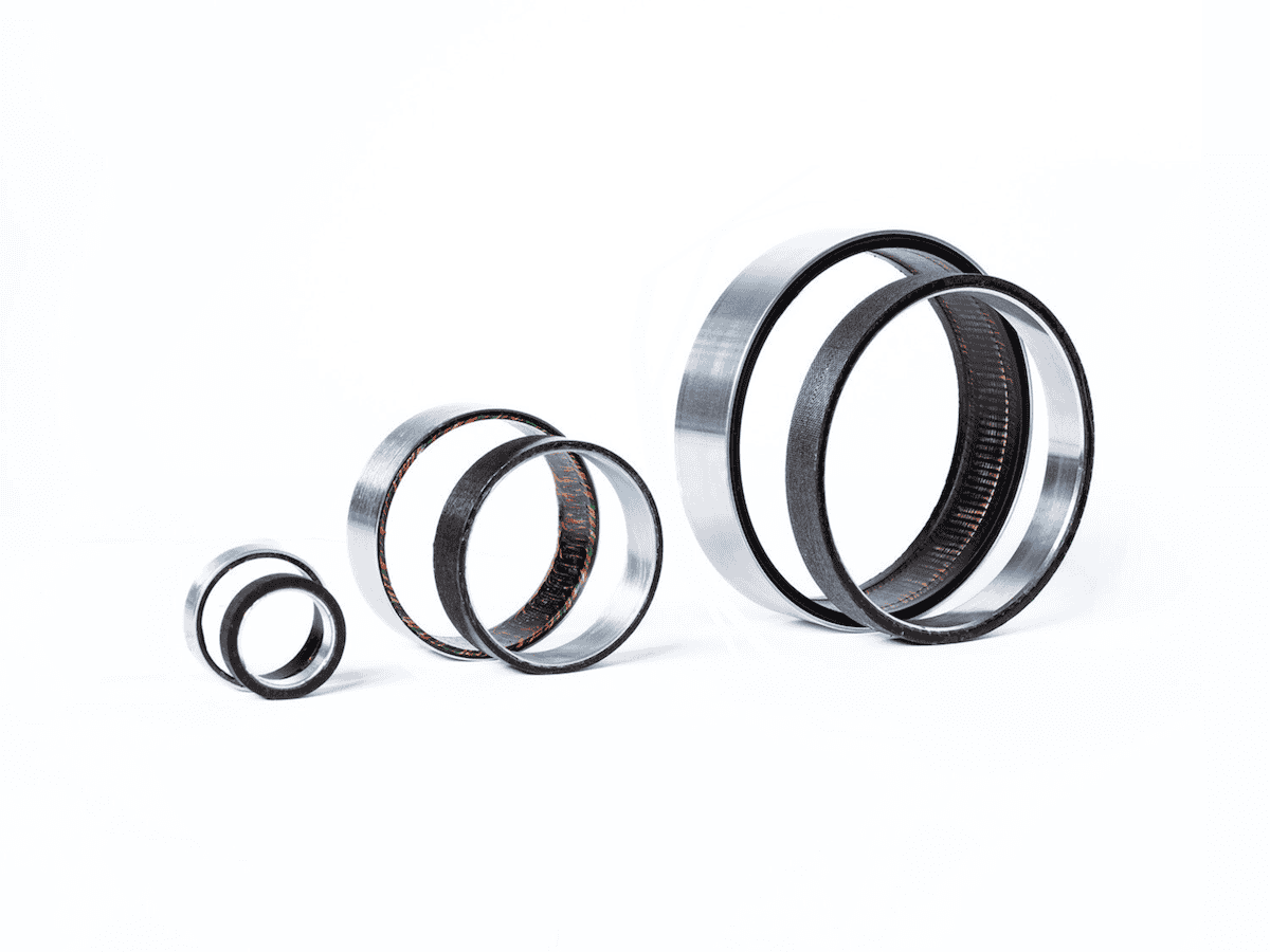


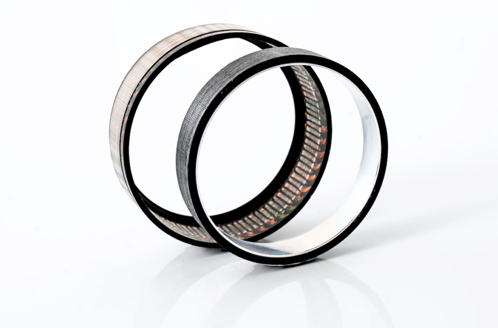
A frameless motor includes only the active rotor and stator parts, lacking an external casing, bearings, and shaft. This design enables easy integration into the mechanical structure of the device it powers. Read more >>
Alva Industries‘ slotless frameless motors, benefiting from FiberPrinting™ technology, feature extremely thin active components, enhancing their suitability for embedded applications. Additionally, slotless motors are less affected by radial misalignment between rotor and stator, simplifying integration in certain cases.
Slotless frameless motors provide various advantages, including enhanced system performance, lower maintenance, compact design, and improved efficiency. Despite these benefits, mounting, installation, and integration processes raise practical questions that require answers.
This article outlines key principles for frameless motor installation, covering typical methods of mounting frameless stators into housings and attaching rotors onto shafts, along with general guidelines for handling, safety, and storage.
Key Pre-Installation Considerations
- Thermal Management: Plan for sufficient cooling as frameless slotless motors, like other motors, generate heat.
- Electrical Interface: Verify motor electrical specifications and compatibility with the electronic controller.
- Mechanical Structure: Ensure the structure supports the motor’s weight, torque, and motion dynamics if the motor is not installed in a fixed position.
Safety Precautions
Frameless motor rotors contain strong rare-earth magnets that generate intense magnetic fields. Individuals with active implants, such as pacemakers, should maintain a safe distance from the rotors.
The magnetic forces attract ferromagnetic materials (e.g., metals), which can result in unexpected movement and potential collisions. All magnetic items should be kept approximately three times the rotor diameter away from the motor.
Additionally, magnetic fields may interfere with or damage electronic devices and storage media; hence, keep rotors away from computers, monitors, and credit cards.
Handling and Storage
Proper handling and storage of motor components are crucial. Stators and rotors should remain in their original packaging until needed. Handle stator assemblies with care to prevent damage to coil insulation and lead wires, which could lead to electrical shorts.
Due to strong magnetic forces, handle the rotor assembly carefully to avoid chipping or breaking magnets if the rotor is dropped or if magnetic objects come into contact with it (including other rotors).
Mounting the Stator into the Housing
- General Considerations: Alva’s motors do not require a soft-magnetic housing due to their magnetic self-sufficiency. Aluminum housings are commonly used, though any suitable material can be chosen. Metal surfaces should be designed to be 2-3 mm away from the motor windings for insulation purposes, and additional space should be allowed for motor leads.
- Grounding: For applications requiring grounding, a ground stud can be placed on the housing, providing a standard grounding scheme. A ground stud is typically only required when the motor is going to operate with no isolation between the mains and the electronic speed controller.
- Stator Retention Methods: Common mounting methods include bonding, clamping, or shrink fitting, each with specific design considerations illustrated in figures for reference.
Press-Fit Stator Retention
Creating an interference fit between the stator and housing and pressing the stator into place is not recommended for Alva’s motors.
If the motor is to be operated over a wide environmental/operating temperature range, use of an interference fit often limits the choice of housing materials to those with coefficients of thermal expansion (CTE) that match the lamination material’s CTE.
Additionally, the pressing process may create burrs that could damage windings and cause electrical faults. Misalignment during pressing may also lead to cracking or splitting of the lamination stack.
Heat Shrink-Fit Stator Retention
In this approach, the housing is heated before placing it over the stator. However, similar issues with material compatibility and thermal expansion arise. Alva suggests using a light interference fit combined with adhesive bonding as a more reliable retention method.
Adhesive Bonded Stator Retention
Adhesive bonding, a commonly used retention method, is recommended by Alva for many applications.
This approach allows diverse material choices for the housing. A 0.2-0.3 mm adhesive groove, covering 50-75% of the stator’s axial length, is recommended for optimal adhesion (Fig. 2).
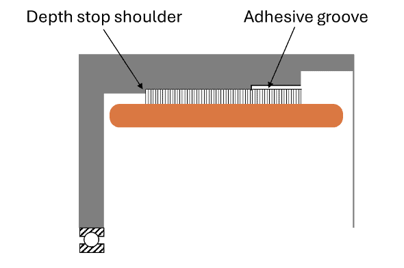
Fig. 2. Concept with adhesive groove.
For an effective installation, it’s recommended to use one of two suggested epoxies, with the process involving heating the housing to 100°C or more. After reaching the required temperature, quickly apply the adhesive into the groove in the hot housing and immediately insert the stator. To finalize, cure the assembly at the epoxy’s cure temperature.
This method allows the housing bore to be designed as a line-to-line fit or with a light interference fit with the stator, depending on the chosen housing material and its coefficient of thermal expansion. Once cured, the adhesive remains compressed at all other temperatures due to its expansion during the initial heated application.
If pre-heating the housing is not possible before installing the stator, ensure the housing bore is designed to be at least 0.003-0.005 mm larger than the stator’s outer diameter, even under worst-case tolerances.
For adhesive selection, Alva can provide guidance. However, 3M DP420 and Hysol E40HT are recommended as toughened, general-purpose structural adhesives suitable for a range of applications.
The concept involving overlapping end cups and the application of bonding adhesive is illustrated in Fig. 3. It is crucial to ensure proper alignment of the stator with the mounting points when utilizing this design.

Fig. 3. The concept with two overlapping end bells and adhesive groove: before assembly (a) and after assembly (b).
Axial Clamping Stator Retention
Axial clamping mechanisms are widely used for securing the stator. Alva’s frameless motor stators have steel banking surfaces on both sides, allowing an axial clamp ring to apply pressure and hold the stator in place. This design facilitates easy removal for maintenance and provides reliable stator positioning.
An axial clamp should be designed to engage the top exposed banking surfaces of the stator, applying consistent axial pressure by being bolted into the housing. The axial clamp can be either a full 360° ring or constructed from a few “servo clamps” to secure the stator stack firmly in place.
One possible concept is presented in Fig. 4, designed to allow easy removal and maintenance access. This setup includes a locating shoulder for precise alignment of the stator, while a gap behind the clamp should be maintained to allow for compression on the stator. At least half of the stator back iron should be engaged with the axial clamp for optimal engagement.
Mounting bolts and washers can be used to secure the stator. Best engineering practices should be followed to determine the appropriate number and size of bolts for the axial clamp, ensuring they meet the torque requirements of the motor. Bolts should be tightened to the specified torque to guarantee reliable and stable assembly.

Fig. 4. Example concept with an axial clamp.
An alternative to the axial clamp is mounting the stator assembly between two end bells, as illustrated in Fig. 5. End bells can be manufactured either by machining from a solid piece of stock or through a die-casting process.
In both cases, the end bells must provide a rigid, stable structure to support both the stator and rotor assembly. This design also facilitates easy removal or access for maintenance, making it practical for various applications.

Fig. 5. Example of stator assembly mounted between two end bells.
Bolt-In Stator Retention
Alva’s frameless motors do not typically employ bolt retention due to the thinness of the lamination ring. Custom configurations can be arranged for specific applications.
Custom Solutions
Custom integration solutions, where the back iron is installed into the customer’s housing with windings inserted in situ, can be arranged upon request (Fig. 6).
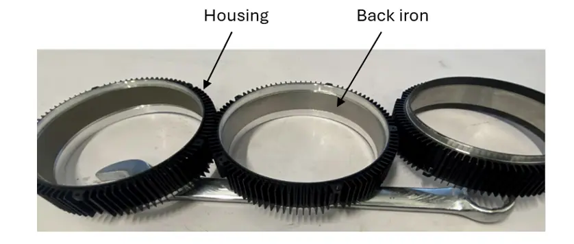
Fig. 6. Molding in frame.
Rotor Mounting
Alva motors utilize Halbach magnet arrays on the rotor, eliminating the need for a magnetic carrying structure.
Rotor-to-shaft mounting can be achieved through several methods, including press-fit, adhesive bonding, and axial clamping, each depending on torque requirements and the rotor’s operating environment.
Press-Fit Rotor Retention
One press-fit method secures the rotor to the carrying structure by creating an interference fit between a set of serrations on the carrying structure and the rotor’s inner circumference. Typically, four serrations are spaced evenly around the outside diameter of the carrying structure, with each serration extending at least three-quarters of the rotor’s length. Tapered serrations may also be used.
The rotor’s inner diameter should match the carrying structure’s outer diameter, with a clearance range between 0.005 mm and 0.05 mm.
An alternative press-fit approach uses a tolerance ring positioned within a special feature on the carrying structure.
During the press operation, apply pressure only to the carrying ring of the rotor—avoiding direct contact with the magnets. A shoulder element on the carrying structure can ensure correct rotor positioning (Fig. 7).
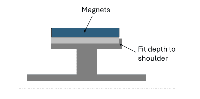
Fig. 7. Illustration of press-fit and shrink-fit concepts.
Heat Shrink-Fit Rotor Retention
This method involves cooling the carrying structure to create a clearance fit, then positioning the rotor onto the structure. Like press fit, this method is also based on designing an interference fit between the rotor and the carrying structure. However, heating the rotor is avoided to prevent magnet demagnetization.
Adhesive Bonding for Rotor Retention
Using high-strength adhesives, the rotor is bonded to the carrying structure, with adhesive grooves providing additional support (Fig. 8). Material compatibility should be evaluated to account for temperature and thermal expansion differences.
This method secures the rotor to the carrying structure using a high-strength retaining compound, such as 3M DP420, Hysol/Loctite E40HT, Loctite 648, or other epoxy-based structural adhesives.
Consult adhesive manufacturers to select the appropriate retaining compound for the specific application. An adhesive groove should be designed on the rotor mating part, typically with a depth of 0.2–0.3 mm. The groove length is generally 50% to 75% of the rotor’s axial length, though various groove configurations are possible (see Fig. 8).
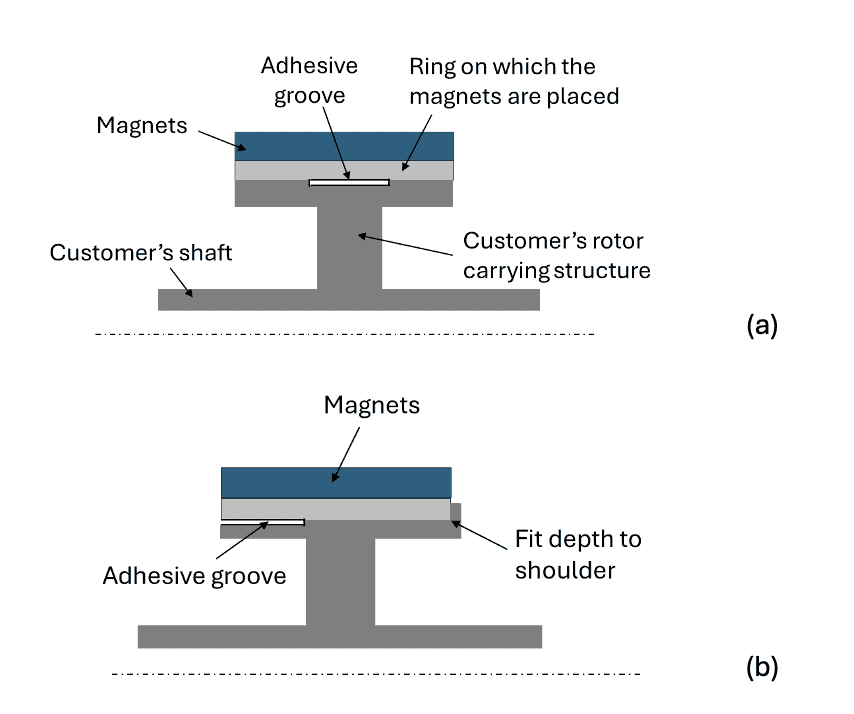
Fig. 8. Concepts employing adhesive bonding.
Adhesive bonding supports a wide range of materials for the mating structure, but differences in thermal expansion coefficients and operating temperatures should be carefully considered.
Axial Clamping for Rotor Retention
This method secures the rotor using a clamp ring that exerts force to hold it in place. To prevent loosening, a lock washer or bonding agent may be utilized. The number of screws needed will vary based on the rotor’s size, torque requirements, and the specific application.
It is essential to avoid clamping directly on the magnet material, as it is quite brittle. Clamping should be applied solely to the magnet-carrying ring, as illustrated in Fig. 9.
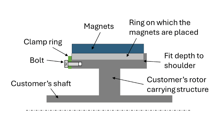
Fig. 9. Axial clamping concept.
Bolt-In and Key-Way Rotor Retention
While bolt-in retention is possible for customized configurations, Alva’s standard rings lack bolt holes. Keyways are not typically recommended due to complexity and over-design for most torque applications, however customers can contact Alva and order special custom ring configurations if desired.

Fig. 10. Bolt–in rotor retention concept.
Custom Solutions
Alva offers solutions for direct magnet mounting onto custom hubs, simplifying assemblies and reducing components.
Practical Assembly Considerations
When assembling the stator and rotor, several practical aspects must be taken into account:
Magnetic Attractive Forces: The magnetic forces between the rotor and stator can be substantial, necessitating careful handling during assembly. To protect both the magnets and the stator windings from potential damage, a thin non-magnetic sleeve (or an equivalent protective device) should be wrapped around the rotor during installation. After successfully installing the rotor within the stator, this sleeve can be removed.
Alignment: Precise alignment of the rotor and stator is critical to prevent imbalances that could affect performance.
Free Rotation: Ensure that the rotor is capable of rotating freely without any contact with the stator or other components.
Post-Installation Checks:
- Temperature Monitoring: During the initial operation, monitor the temperatures of both the motor and gearbox to confirm that adequate cooling is maintained.
- Testing: Power on the motor and conduct initial tests to verify proper operation and alignment between the rotor and stator.
- Vibration Check: Monitor for any unusual vibrations, which may indicate misalignment or other issues that require attention.