


In this article Tyto Robotics explains how to increase (or decrease) electric drone motor speed, motor speed in terms of Pulse-Width Modulation (PWM) duty cycle and Electronic Speed Controller (ESC) output voltage, and the motor KV to RPM calculation.
Electric motors are used in many tools and vehicles. In drones and electric aircraft, they are most often controlled with a throttle controller and ESC.
When you increase the throttle on your controller, what you are doing is increasing the amount of electrical power drawn from your power supply (i.e. battery) and fed to your motor via the ESC. If you want to slow down the motor, reduce power; If you want to speed up the motor, crank up the power.
But what is the mechanism behind controlling the motor’s speed?

How to Increase (or Decrease) Electric Motor Speed
Controlling electric motor speed is as “simple” as controlling the amount of electrical power delivered to the motor. In the following article, we are going to assume that we are looking at a steady state condition where there is no acceleration.
To be more precise, for a given mechanical load (or resistance), it is the increase in voltage that leads to the increase in speed. Alternatively, we can reduce the load on the motor.
If we look at this equation for angular velocity:
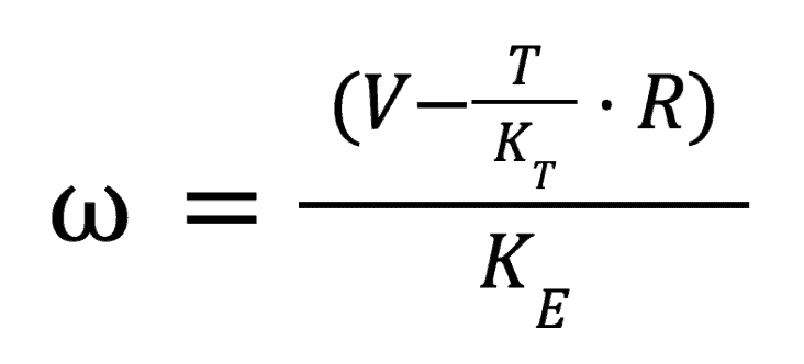
Where:
ω = angular velocity
V = voltage
T = torque
Kᴛ = motor torque coefficient
R = resistance / load
Kᴇ = back EMF constant of the motor
We can see that the angular velocity, (AKA motor speed, AKA RPM), is proportional to voltage and negatively proportional to torque.
Therefore, if we want to increase the motor’s speed we can either a) increase the voltage delivered or b) decrease the torque. Since decreasing the torque would require changing your design or load, it is much simpler to increase the voltage.
The equation also demonstrates that at a constant voltage, a higher torque results in a lower RPM.
We should also note that there are some minor losses within the ESC, so the input voltage is higher than the output voltage to the motor, but usually only by a few percent.
Motor Speed in Terms of PWM Duty Cycle and ESC Output Voltage
We can also describe this process of changing motor speed in terms of the ESC protocols used to deliver the power.
With PWM, for example, the value sent from the controller (in µs), corresponds to a percentage of the maximum voltage that can be sent to the motor and the ESC.
The PWM value in µs will be between 1000 (no throttle) and 2000 (full throttle). All of the values in between have a signal length in µs, which correspond to a duty cycle between 0 and 100%.
At 0%, there is no power delivered to the ESC and motor. At 100%, power is constantly delivered to the ESC and motor.
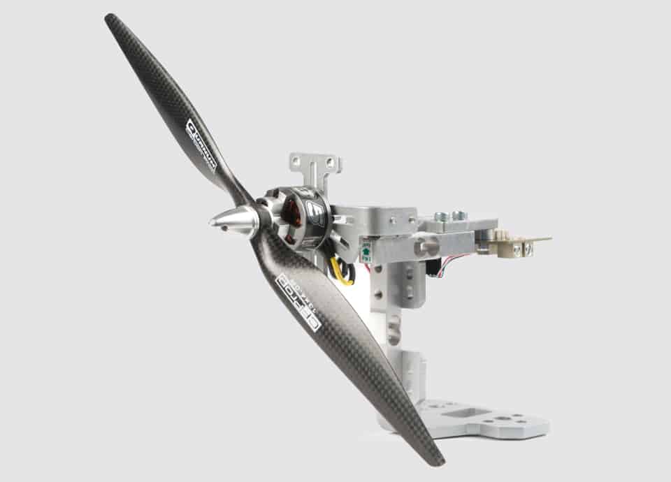
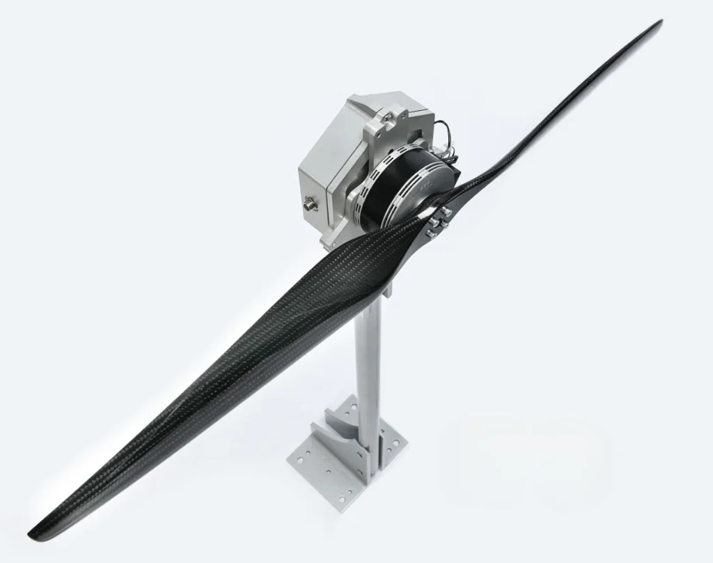
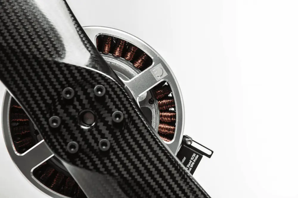
Xoar TA130 motor mounted on test stand
There is variation in this implementation by ESC manufacturers. However, the relationship between duty cycle and motor speed is usually roughly equivalent to the average output voltage of the ESC.
The ESC approximates a sine wave output on each phase. At 50% ESC output, the sine wave will have about half the amplitude of the sine wave at 100% ESC output. Note that the electronics drivers on most ESCs only have an on-off state, so the actual signal is not as smooth as a perfect sine wave.
There are many variations between motor and ESC manufacturers, and the electronics can introduce non-linearities. For practical applications, it is best to characterize the motor and ESC using a dynamometer.
Digital protocols like Dshot and Oneshot use the same duty cycle concept, but with much faster signal delivery and different signal delivery patterns.
You may also see the duty cycle written as a value between 0 and 1024. This is based on the fact that the technology was developed around 8-bit controllers. 2 options (on / off) with an 8 bit system → 2¹⁰ → 1024.
This system can also be used to determine the ESC’s output voltage.
For example, 796 → 78% ‘on’ relative to a 100% output.
Motor KV to RPM Calculation
In a no load condition, you can use the motor’s KV value to estimate the motor’s speed based on the voltage delivered.
As discussed in our article on how to calculate motor KV, we can replace Back EMF with input voltage in this equation to estimate the rotation speed of our electric motor.

Let’s use MAD Components’ M50C35 EEE 9 KV motor as an example. It has a max voltage of 400 V and a KV rating of 9 KV. Plugging these numbers into the formula we get a max speed of:
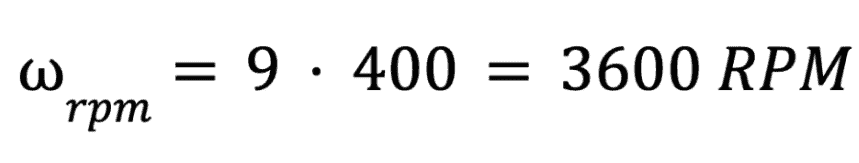
So at max throttle, this motor will rotate at 3600 RPM. If we applied only 75% throttle, corresponding to 300 V, it would rotate at a speed of 2700 RPM.
Conclusion
As demonstrated in this article, there are a few ways to increase motor speed.
The most actionable way is to increase voltage delivered to the motor by increasing the throttle. You can also decrease the torque, but this is generally more disruptive to the design or purpose of the UAV.