


In the following article, Tyto Robotics explains the two different ways of approaching the vibration problem in drone test stands: simulation and experimental testing.
Vibration is a common obstacle that needs to be overcome when building drones. Excessive vibration can cause issues in flight or during testing.
In this article, we are going to demonstrate two ways of approaching the vibration problem in drone test stands: simulation and experimental testing. The solution we used to change the fundamental frequencies using dampers is similar to what you would use with a drone.
Background – Designing the Flight Stand
We recently released the new Flight Stand 15/ 50, a thrust stand/ dynamometer made for testing drones that can handle loads up to 50 kgf of thrust. The stand has a hollow tube structure in order to offer better aerodynamics as well as improved cable management, with cables running inside the tube instead of along the outside.
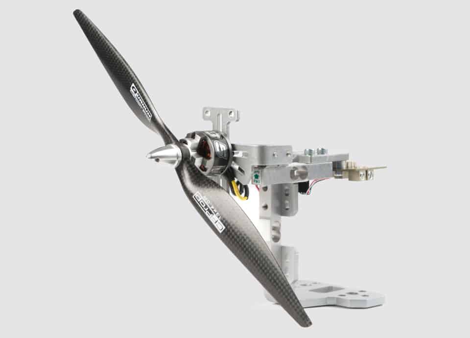
An outstanding challenge in designing the test stand was limiting the amount of vibration during propulsion testing. As mentioned, the stand’s basic shape is a vertical tube that must house a Force Measurement Unit (FMU) and hold a motor and propeller mounted at the top (figure 1). The stand is used to test motors and propellers, which inherently induce vibration, potentially damaging the tool. To optimize and protect the stand, we performed a series of vibration tests similar to those used for drone components such as quadcopter arms. Our experimental procedure and results are outlined in this article.
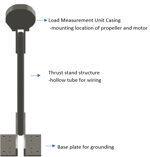
Figure 1: Early design concept of the Flight Stand
Vibration of the Test Stand
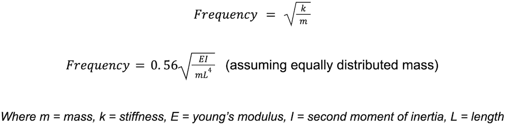
The test stand is adaptable to the customer’s motors and propellers, and with this comes variation in the design parameters. One parameter with a strong influence on the frequency of the system is overall mass. The equations below show how an increase in mass will decrease the natural frequency of the system. The stand can measure a large range of thrusts, therefore different masses of propellers and motors will be used. Depending on the user’s propeller and motor mass, the natural frequency will change [1]:
Due to variations in the mass, propeller size and thrust of testable propulsion systems, the thrust stand has the potential to operate in a wide range of frequencies. With this, the resonant frequency of the structure may fall within the operating range of the stand.
Resonance occurs when the natural frequency of a structure is excited, resulting in a larger amplitude of vibration or what can be seen as greater movement in structures. Maintaining that frequency results in increased excitation and can lead to structural damage or failure. A common example of the danger of resonance is the Tacoma bridge collapse of 1940. While there were several reasons for the collapse, a major contributor was the resonance that caused the bridge to twist and move uncontrollably.
Vibration Simulations
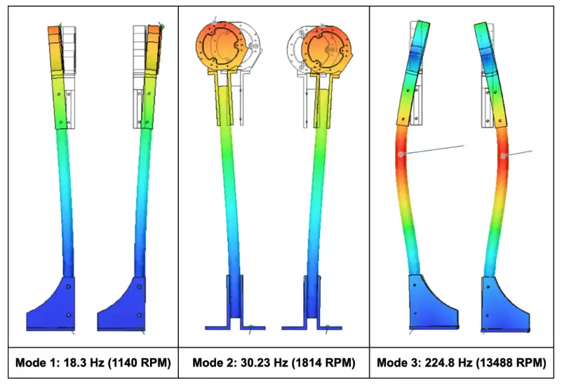
When designing the stand, we noted that the natural frequency would fall within the range of operation. The thrust stand has the ability to measure anywhere from 1.5 kgf to 50 kgf, which corresponds to propellers that can be run anywhere from 1,000 – 10,000+ RPM, correlating to frequencies of approximately 16 Hz – 200 Hz.
We ran some vibration simulations in order to observe the stand’s reaction to various vibration modes, shown in figure 2. The vibration modes represent the motion that will occur if a certain vibration is maintained. It is important to refrain from operating the stand in these modes for extended periods of time to avoid resonance.
Experimental Testing
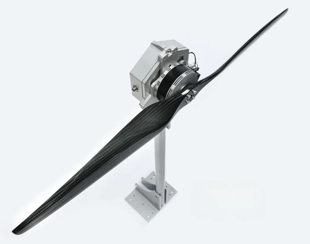
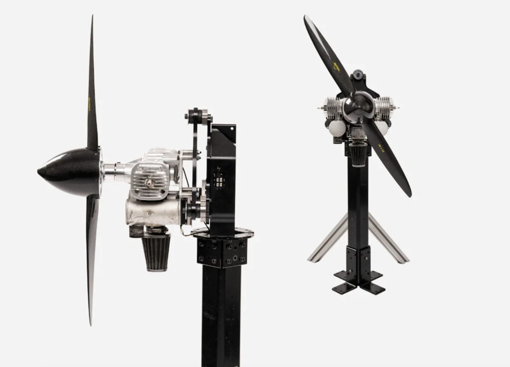
A prototype stand was built to allow for a better understanding of how these vibrations would impact the stand in practice. While simulations are very helpful, it is important to see how the stand is affected by vibrations during real tests. The stand in figure 3 was assembled and tested with an adaptable motor mount at the top instead of the FMU. A propeller trimmed on one side was used to create imbalance in the system.
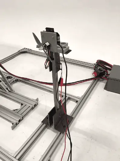
Figure 3: Prototype thrust stand for vibration testing
The vibration dynamics were recorded using the Flight Stand software. One key observation was the importance of a stable base. When the stand is not securely attached to the ground, the base experiences more movement, resulting in a lower resonant frequency and higher vibration readings. Figure 4 shows how the resonant frequencies can be determined through testing. After the motor is started and the propeller speed is slowly increased, large jumps in vibration can be observed throughout the test, which can be associated with resonance.
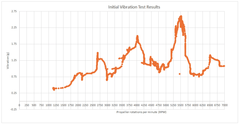
Figure 4: Vibration of the thrust stand with increasing propeller speed
Typical damping methods such as sandwich mounts were considered, however vibration dampers must be used in the same direction that vibration occurs. The locations available on the stand for mounting damping are in the vertical direction, but vibrations primarily occur laterally, posing a challenge.
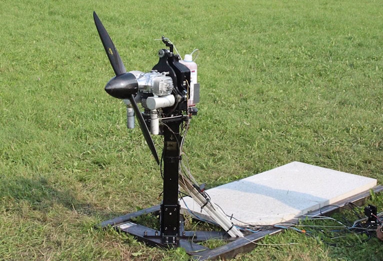
The initial tests were run on a prototype that was designed and assembled in house. A second round of tests was run with an official prototype, machined in a shop with correct tolerances and fit. During these tests there was minimal noise and the stand was very rigid. As in the previous test, we observed that the stability of the base was very important.
With the stand secured directly into concrete, the stand experienced very little vibration and there was minimal noise at the highest vibration recorded. When mounted to the rails, there was still minimal noise and movement in the stand but the vibration reading was higher and the stand was slightly less stable. If there are significant vibration or noise issues with the stand mounted on the railings, we recommend adding more concrete fasteners to limit movement in the rails.
Vibration in Drones
Similarities can be found between the vibration observed in the thrust stand and that observed in drones. In both cases, vibration is caused by the movement of the propeller and motor, with added complexities for drones because they are designed to have constant motion and carry fragile electronics. Drones are equipped with many sensors to monitor the system and provide useful data about the vehicle’s position and speed, but additional testing in the lab can help predict and prevent vibration-based damage to the structure and to the fragile electronic components.
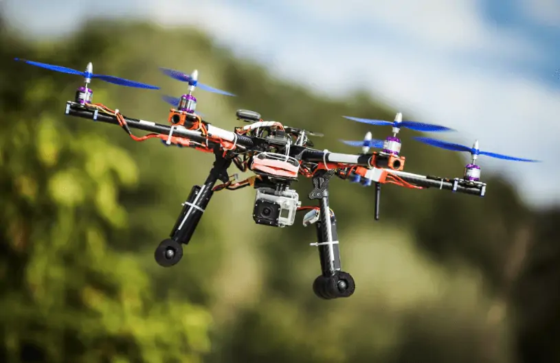
Figure 5: A drone in flight with a camera load
The vibration analysis of a multi-rotor frame is explained in depth in reference [2] with some similarities to the tests described in this article. First, a propulsion experiment is conducted to determine the rotational speed at which the propeller induces the most vibration. With this information, a simulation modal analysis is completed followed by an excitation experiment to see how the frequencies impact the system.
Conclusion
As demonstrated, the vibration testing process is similar for thrust stands and drone components. Simulation and calculations are an important part of the process, followed by experimental testing. These experiments can provide important insight for designers and can ultimately help reduce vibration in test tools and the aerial vehicles they test.
References
[1] Engineering ToolBox, (2017). Beams Natural Vibration Frequency. [online] Available at: https://www.engineeringtoolbox.com/structures-vibration-frequency-d_1989.html
[2] J. Verbeke, S. Debruyne, “Vibration analysis of a UAV multirotor frame,” In Proc. ISMA2016, 2016, pp.2329-2338.