Doodle Labs has released a guide to educate customers on the decisions they will need to make when choosing an antenna for a communication system, including frequency and bandwidth, polarization, gain and directivity, and form factor.
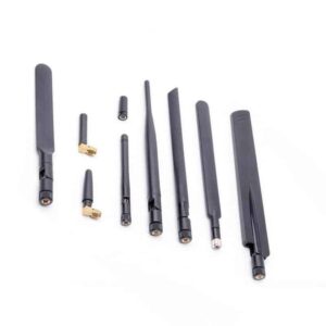
When designing your communications system, the most important choice is what radio you choose. But it’s closely followed by the antennas you use with it.
We could give you the best radios in the world for your system (which we believe we do), but without using antennas suited to your application the entire system could fail or give you significantly worse results that you’d expect.
Unfortunately, there isn’t a simple answer to “what is the best antenna to use with the Smart Radio”. Indeed, the answer is “it depends on what you’re trying to do”.
This is a quick guide to educate you on the various decisions you’ll probably need to make when choosing an antenna. If you’d like to do basic indoor testing, then we recommend using our Evaluation Kits for simplicity.
If you’d like recommendations on what antennas to use for your application, please contact us and share some detail around your project. We’ll do our best to steer you in the right direction.
The sections below outline the major decisions you’ll have to make when selecting an antenna:
- Frequency and Bandwidth
- Polarization
- Gain and Directivity
- Form Factor
Frequency and Bandwidth
Most often, our customers already know the frequency band they have access to as they had to choose it prior to selecting the Smart Radio they’ll be using. The application, geography, and end-user inform the decision on which frequencies to pursue. The table below lists some of the Smart Radios and their frequency ranges, and the Models Index has a complete list.
| Model No. | Frequency Range (MHz) | Description | View Specs |
| RM-915-2X |
902-928 MHz |
License Free ISM Band – USA, Canada, Mexico, Central, South and Latin Americas, Australia, New Zealand and China | View Datasheet |
| RM-2450-2X |
2400-2482 MHz |
License free ISM Wi-Fi band (Worldwide) | View Datasheet |
| RM-5800-2X |
5725-5875 MHz | License Free ISM band – USA, Canada, Mexico, Central, South and Latin Americas, Australia, and New Zealand | View Datasheet |
| ACM-DB-3 |
2.4 & 5.8 GHz |
License Free ISM Bands |
View Datasheet |
| NM-DB-3 |
2.4 & 5.8 GHz | License Free ISM Bands | View Datasheet |
| ACM-DB-2 |
2.4 & 5.8 GHz | License Free ISM Bands | View Datasheet |
| NM-DB-2 |
2.4 & 5.8 GHz | License Free ISM Bands | View Datasheet |
Some antennas are capable of covering multiple frequency bands; they may have a wide overall bandwidth and will have smaller center bands. For example, you can have an antenna that covers 698 MHz to 3 GHz and has six bands within that range that it is designed to operate at.
The tradeoff, of course, is that the performance may not be the best for any given frequency, but it offers a variety of usable frequencies in a single package. Our recommendation, especially for your final design, is to use an antenna that targets only the frequencies you’ll be operating at.
Something to keep in mind, especially for size and weight constrained customers, is that the operating frequency significantly impacts the size of antenna. Higher frequencies have smaller wavelengths, and thus their antenna size will typically be smaller than lower frequency antennas.
Polarization
The Smart Radio is a MIMO radio system that can leverage multiple types of antenna polarization schemes to improve diversity, which is one of the primary methods of providing robust connectivity in challenging environments.
All antennas have a polarization direction, which is the oscillation direction of the radiation as it leaves the antenna.
Linear and Circular Polarization
Linear polarization occurs in a straight line and, depending on the direction the antenna is pointing, will be vertical, horizontal, or any angle in-between. The electrical wave of the antenna’s signal oscillates up and down along the axis of this straight line.
Circular polarized radiation rotates as it leaves the antenna (similar to a corkscrew) instead of moving on a single plane. Circular polarization can either rotate clockwise or counterclockwise. Antennas that are circularly polarized are often better suited for operating in inclement weather conditions, as they can more easily pass through rain and other atmospheric disturbances compared to linear polarized antennas. Circularly polarized antennas also help in rapidly moving scenarios, such as drones, where the orientation of the antennas is constantly changing.
The choice of antenna polarization is important because transmit and receive antennas need to be the same polarization type. If a vertically polarized antenna is used with a circularly polarized antenna, a loss of gain will be introduced, thereby reducing communication distance and impacting the quality of video or data transmission.
Cross Polarization for Diversity
Isolating each data stream in a MIMO radio helps increase diversity and improve transmission quality. This can be done by utilizing opposite polarizations within each set of antennas on the radio.
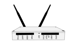
For example, a Smart Radio can be configured to use two linearly polarized antennas that have 90 degree orthogonal polarization between them. On the receive side, the antennas can be configured to match the same 90 degree positioning in order to receive the signal without issue. Cross polarization helps provide additional reliability when the orientation of the antennas is dynamic, such as in drones and ground robots.
Gain and Directivity
Antenna gain can be thought of as a “push” for a signal coming from the radio. Higher gain leads to better signal quality, higher data throughput, and longer range. As such, one should aim for the highest possible gain that provides the directional coverage needed and is allowed by local EIRP regulations.
Gain is often measured in dBi. For example, 10 dBi means 10 times the energy compared to an isotropic antenna, which radiates power evenly in all directions.
In a passive antenna, gain is built by directing the antenna’s radiation in a certain direction (as opposed to evenly in all directions like an isotropic antenna). This increases the strength of the “push” at the expense of not radiating in all directions. The higher the gain, the larger the antenna.
Mobile Robotics and UAV customers should consider the height at which their vehicles will be moving and look for an antenna that maximizes horizontal gain while still providing the required spatial coverage.
Drone system designers will often utilize low gain omni antennas (e.g. 3 dBi) that are pointed downwards to keep the weight down on the flyer. On the ground, a higher gain omni or tracking antenna pointed upwards will be used.
Form Factors
Two types of antennas are discussed below: omnidirectional and directional. The choice of form factor is primarily driven by the directivity discussed above.
Omnidirectional Antennas
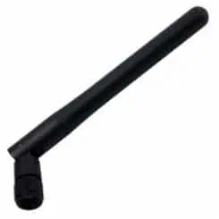
Omnidirectional antennas are designed to radiate equally in all directions on a single plane. This class of antenna is versatile and is suitable for many applications where the nodes are mobile and where movement is random. The black rubber ducky antenna you probably see at the back of your home router is an omnidirectional antenna.

 Directional Antennas
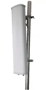
As the name implies, a directional antenna is designed to focus its radiation in a certain direction. This increases the gain and minimizes interference from other directions. Sector antennas, for example, focus their coverage up to 180°.
Long-range antennas are a subclass of directional antennas, where their design and construction are primarily for long distance point to point connections. Coverage angles range typically between 12° and 25°, so the antenna must be pointed quite precisely at the other antenna. If a very long link is required for a UAV, then a dish antenna can be used with tracking technology to ensure that it is constantly pointed towards the flyer.


